Eureka AIR delivers breakthrough ideas for toughest innovation challenges, trusted by R&D personnel around the world.

Air bag module with locking member for locking the position of a vent member

a technology of airbag module and vent member, which is applied in the direction of vehicular safety arrangement, vehicle components, pedestrian/occupant safety arrangement, etc., can solve the problems of reduced pressure within the airbag, increased inflation fluid pressure,

Inactive Publication Date: 2008-04-29
TRW VEHICLE SAFETY SYST
View PDF36 Cites 38 Cited by
  • Summary
  • Abstract
  • Description
  • Claims
  • Application Information

AI Technical Summary

Benefits of technology

[0008]In accordance with another aspect, the present invention relates to a vehicle occupant protection apparatus comprising an inflatable occupant protection device and a support member. The support member has a vent opening through which inflation fluid may flow. The vehicle occupant protection apparatus also comprises means for controlling a flow of inflation fluid through the vent opening for (i) reducing a force that is applied by the inflatable occupant protection device to an occupant prior to the inflatable occupant protection device inflating to a predetermined distance and (ii) helping to maintain pressure within the inflatable occupant protection device after the inflatable occupant protection device has inflated beyond the predetermined distance. Inflation fluid pressure within the inflatable occupant protection device tends to move the means for controlling for increasing a flow of inflation fluid through the vent opening.

Problems solved by technology

The interaction of the occupant and the air bag may result in a sudden increase in the inflation fluid pressure within the air bag.
If not impeded, the increased flow of inflation fluid through the vent opening may result in the pressure within the air bag becoming lower than desired for the air bag to restrain the occupant.

Method used


Image

  • Air bag module with locking member for locking the position of a vent member
  • Air bag module with locking member for locking the position of a vent member
  • Air bag module with locking member for locking the position of a vent member

Examples


Embodiment Construction

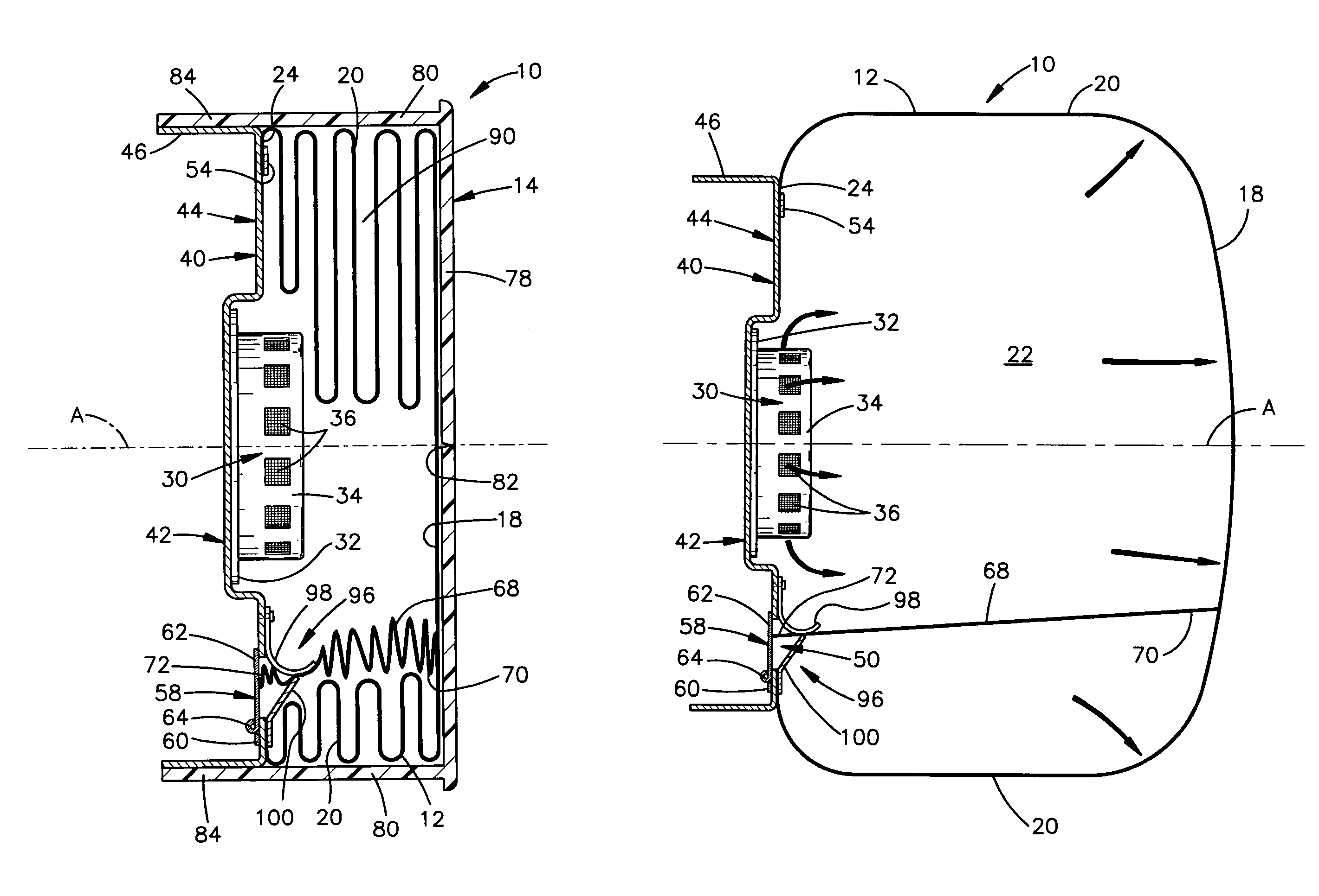
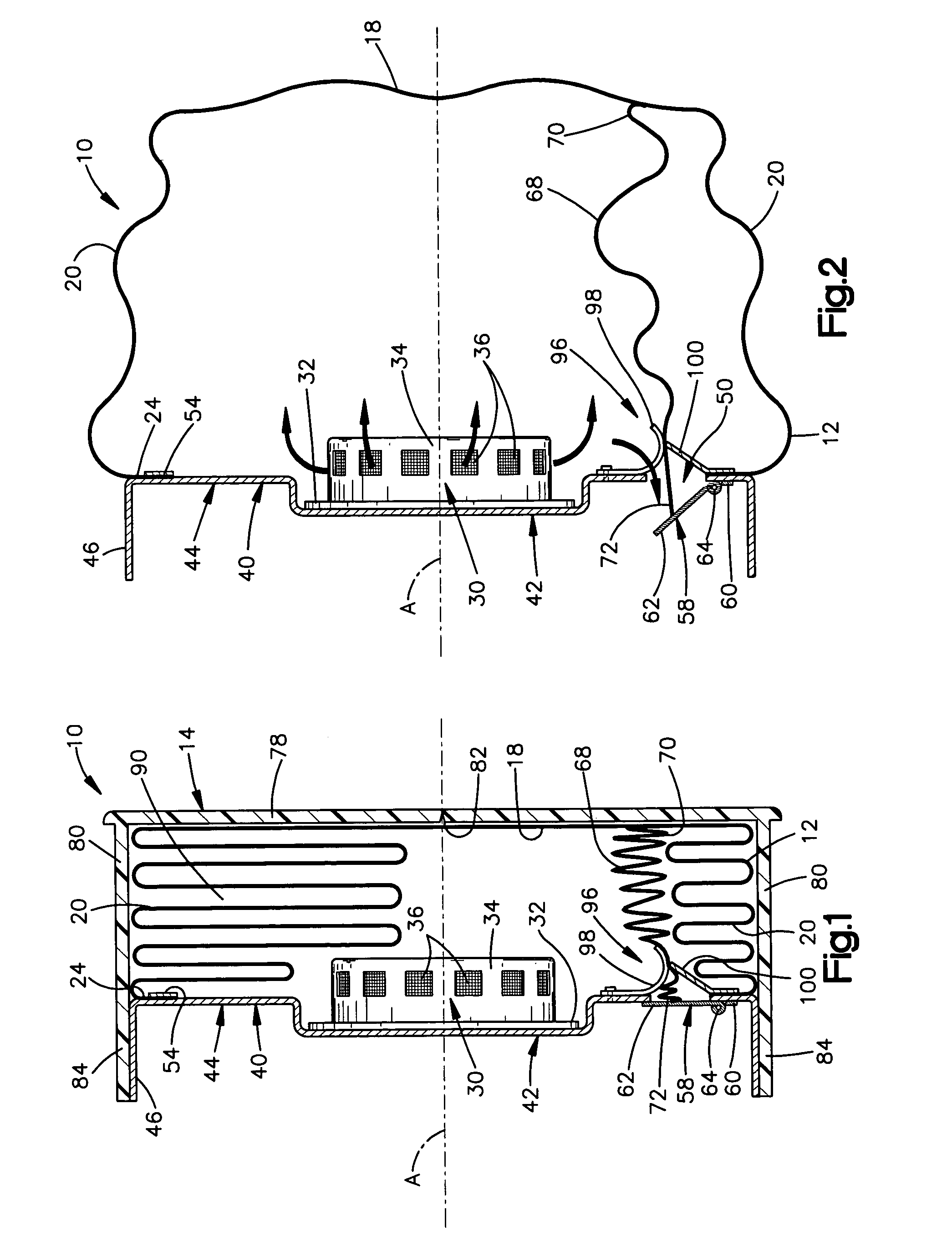
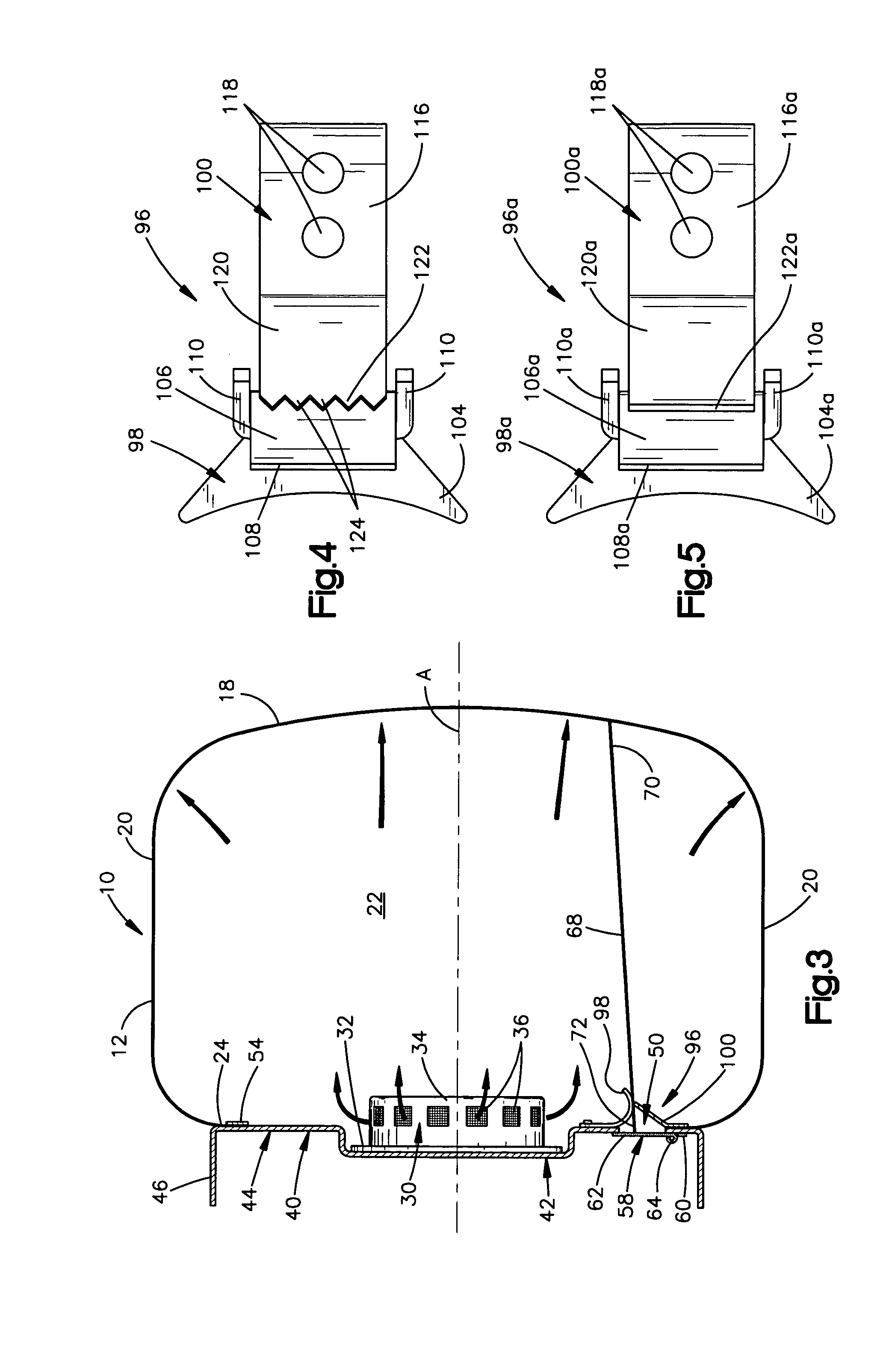
[0033]FIG. 1 is a sectional view of a vehicle occupant protection apparatus 10 constructed in accordance with the present invention. The vehicle occupant protection apparatus 10 of FIG. 1 is an air bag module. The air bag module 10 includes an inflatable occupant protection device in the form of an air bag 12. As an alternative to an air bag, the inflatable occupant protection device may be, for example, an inflatable seat belt, an inflatable knee bolster, an inflatable head liner, an inflatable side curtain, or a knee bolster operated by one or more inflatable air bags.

[0034]The air bag 12 is preferably made from a flexible fabric material, such as woven nylon. The air bag 12 can alternatively be made from a non-woven material, such as plastic film. The air bag 12 has a deflated and stored condition in which the air bag is packed and stored within the air bag module 10, as shown in FIG. 1. In response to receiving inflation fluid, the air bag 12 inflates from the deflated and store...


PUM


Abstract

A vehicle occupant protection apparatus (10) includes an inflatable occupant protection device (12) and a support member (40) having a vent opening (50) through which inflation fluid may flow. The apparatus (10) also includes a mechanism (58) for controlling a flow of inflation fluid through the vent opening (50). Inflation fluid pressure within the inflatable occupant protection device (12) tends to move the mechanism (58) for increasing a flow of inflation fluid through the vent opening (50). The mechanism (58) is responsive to inflation of the inflatable occupant protection device (12) beyond a predetermined distance for restricting the flow of inflation fluid through the vent opening (50). The apparatus (10) further includes a locking member (96) for blocking the mechanism (58) from increasing the flow of inflation fluid through the vent opening (50) after the inflatable occupant protection device (12) has inflated beyond the predetermined distance.

Description

RELATED APPLICATIONS[0001]This application is a continuation-in-part of copending patent application Ser. No. 10 / 244,933, filed Sep. 16, 2002 now U.S. Pat. No. 7,083,191.TECHNICAL FIELD[0002]The present invention relates to a vehicle occupant protection apparatus. In particular, the present invention relates to an air bag module having a vent member that is moved during inflation of an air bag and a locking member for locking the position of the vent member.BACKGROUND OF THE INVENTION[0003]It is known to provide air bag modules with vent openings through which inflation fluid may be discharged. When an occupant of a vehicle is positioned too close to the air bag module and is contacted by an inflating air bag, the vent openings enable some inflation fluid to be discharged from the air bag to atmosphere. The discharge of inflation fluid through the vent openings helps reduce the contact force between the inflating air bag and the occupant.[0004]It is also known to associate a vent do...

Claims


Application Information

Patent Timeline
Patent Type & Authority Patents(United States)
IPC IPC(8): B60R21/276B60R21/16B60R21/217B60R21/233B60R21/2338
CPCB60R21/233B60R21/2338B60R21/276B60R21/217B60R21/2342B60R2021/23382B60R2021/2765
Inventor BRAUN, WILLIAM P.FISCHER, KURT F.STEFFENS, JR., CHARLES E.MEDUVSKY, ALEX G.CLARK, JOHN N.ZWOLINSKI, JOSEPH J.FRANK, MATTHEW C.
Owner TRW VEHICLE SAFETY SYST
Why Eureka
Eureka Blog
Learn More