
Sit to stand support apparatus

a technology of support apparatus and sitting position, which is applied in the field of sitting support apparatus, can solve the problems of high risk of injury for both the patient and the assisting personnel, the patient could lose support lifting themselves or being lifted and sustain a fall, and the prior art mechanical devices do not address the true nature of motion required

Inactive Publication Date: 2008-04-15
SUMMERS PATRICK D
View PDF43 Cites 32 Cited by
  • Summary
  • Abstract
  • Description
  • Claims
  • Application Information

AI Technical Summary

Benefits of technology

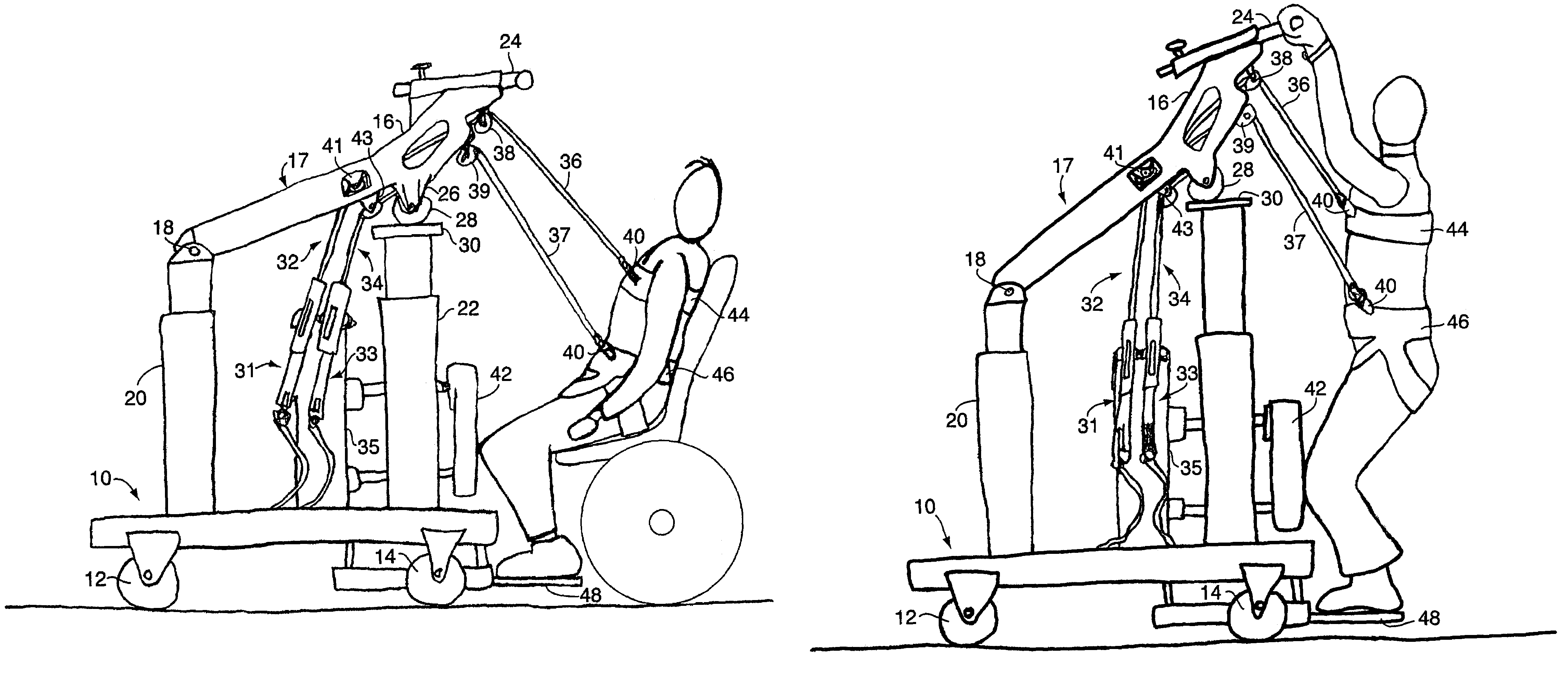
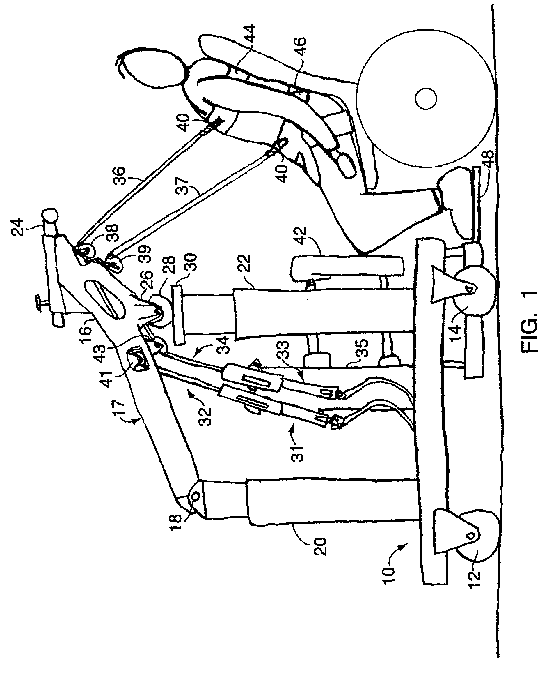
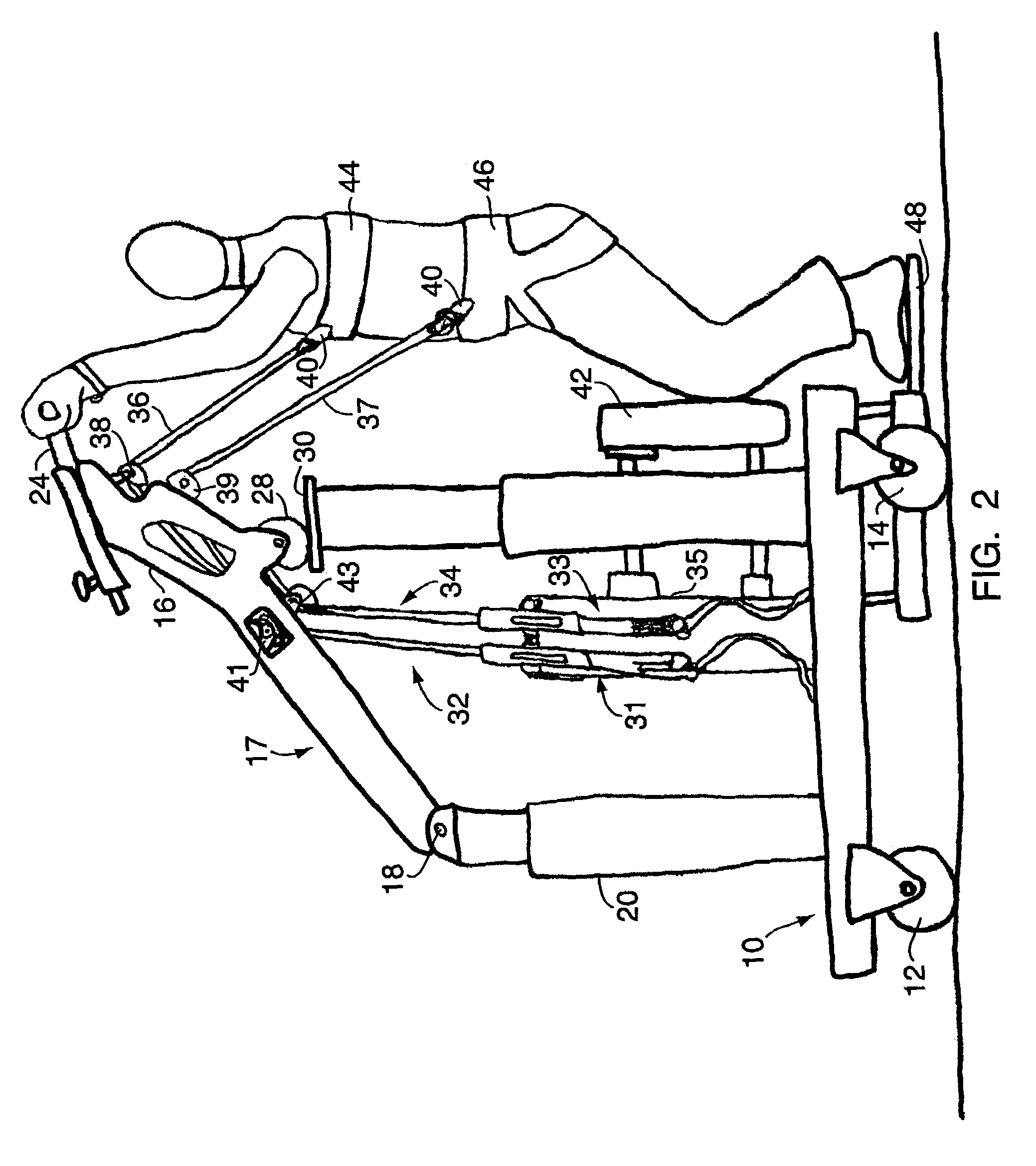
"The invention is a support apparatus that helps patients stand up from a seated position. It has a chassis, support piers, and driving piers with roller platforms for raising and lowering. There are also beams with rollers for lifting the patient's arms and legs, and a kneepad for added leverage. The apparatus can be easily moved and has a foot tray for the patient to stand on. The block and tackle devices have a cable locking system to keep the cable aligned as the beam is raised and lowered. The technical effects of this invention are improved mobility and stability for patients, making it easier to stand up and walk around."

Problems solved by technology

If supported solely by nursing or therapy personnel, there is a higher risk of injury for both the patient and the assisting personnel.
Patients could lose support lifting themselves or being lifted and sustain a fall.
Prior art mechanical devices also do not address the true nature of motion required to move from a sitting to a standing position.
In fact, it is complex.
Prior art devices either lifted by the upper torso only, which can possibly overload the delicate upper body structure (most commonly the axillary [armpit] area and specifically the shoulder joints and tendons), or by the upper torso and hips, which when employed at the same angle and speed during the lift tends to keep the patients in a crouching or semi-crouching position.
However, instabilities inherent in lifting patients who are large or obese and those who are unable to maintain their own balance, may cause lateral forces to be exerted on the boom as it moves through its vertical arc.
Such lateral forces may tend to cause a shifting of the patient's center of mass, which in turn may cause the undesirable side loading of the actuators.
Such side loading may contribute to the instability of the device and may compromise the structural integrity of the actuators.

Method used


Image

  • Sit to stand support apparatus
  • Sit to stand support apparatus
  • Sit to stand support apparatus

Examples


Embodiment Construction

[0019]The contents of U.S. Pat. No. 5,174,590 and provisional patent application 60 / 579,293 (docket number 5196-002, Enduro Medical Technology Sit to Stand Support Apparatus), are incorporated herein by reference in their entireties.

[0020]The present invention is a chassis structure having a boom that comprises dual parallel beams that are simultaneously rotated about pivot points by substantially vertical upright dual driving piers. The beams are pivotally supported at dual support piers, the support piers being telescopically adjustable in height to allow for the overall height adjustment of the apparatus. The driving piers are telescopingly extendable to rotate the beams about the pivot points. The chassis is positioned such that the patient is at the non-pivoting ends of the beams when the patient is in a sitting position. Ropes, cables, chains, or wires are fixed to the chassis and extend over support surfaces at or near the free (non-pivoting) ends of the beams to connect to a...


PUM


Abstract

A rolling chassis supports dual lifting beams pivotably mounted on adjustable supporting pins. The beams are pivoted by rollers raised by dual driving piers. Each beam carried a pair of blocks for a rope running from a locking system on the chassis to one side of an upper harness, and another pair of blocks for a rope running from a locking system on the chassis to one side of a lower harness. A retractable knee pad assists lifting a patient from sitting to standing position as the beams pivot and retract the cables.

Description

CROSS REFERENCE TO RELATED APPLICATION[0001]This application claims the priority of pending provisional application Ser. No. 60 / 579,293 filed Jun. 14, 2004.TECHNICAL FIELD[0002]This invention relates to ambulation assistance devices and, more particularly, to an apparatus that assists a person moving between sitting and standing positions.BACKGROUND OF THE INVENTION[0003]In the past, patients needing assistance to reach standing positions had to depend upon human or prior art mechanical support. If supported solely by nursing or therapy personnel, there is a higher risk of injury for both the patient and the assisting personnel. Patients could lose support lifting themselves or being lifted and sustain a fall. Nursing or therapy personnel could sustain back or other muscle injuries while preventing the patient fall or while in the act of lifting and moving the patient, especially when a patient is an obese or morbidly obese person (morbidly obese being at least two times the recomme...

Claims


Application Information

Patent Timeline
Patent Type & Authority Patents(United States)
IPC IPC(8): A61G7/10A61G5/14A61G7/14
CPCA61G7/1015A61G7/1046A61G7/1051A61G7/1069A61G7/1094A61G7/1096A61G7/1078A61G2200/34A61G2200/36A61G2200/52
Inventor SUMMERS, PATRICK D.
Owner SUMMERS PATRICK D
Learn More