Eureka AIR delivers breakthrough ideas for toughest innovation challenges, trusted by R&D personnel around the world.

Method and apparatus for signal separation

a signal separation and signal technology, applied in the field of spread spectrum communication, can solve the problems of co-channel interference between the transmitted cdma signals, the inability to achieve complete orthogonality in practice, and the degraded transmission quality of cdma signals in such systems

Active Publication Date: 2008-04-08
GENERAL DYNAMICS MISSION SYST INC
View PDF4 Cites 15 Cited by
  • Summary
  • Abstract
  • Description
  • Claims
  • Application Information

AI Technical Summary

Problems solved by technology

However, transmission quality of CDMA signals in such systems typically degrades when the signals travel over more than one path between the transmitter and the receiver.
This is because such “multi-path propagation” causes co-channel interference between the transmitted CDMA signals.
This limitation is caused by user interference dominance over additive thermal noise.
However, because multiple signals often are not time aligned, complete orthogonality is usually not achieved in practice.
As a result, interference between otherwise orthogonal signals occurs.
Rigorous analysis of multiple signal interference space may be further complicated by co-channel interference from signals having analytic and bandpass properties that are unknown.
Separation of co-channel and adjacent channel interference in a mobile environment may be further complicated by fading and Doppler effects.
The separation of independent sources from an array of sensors is a classic and difficult problem in signal processing.
This is generally known as a “cocktail party” problem, since a person generally wishes to listen to a single sound source while filtering out other interfering sources, including multi-path signals.
However, in mobile communications, the signals are subject to fading.
For example, obstacles such as buildings interfere with signal path and create reflections.
A cluttered, interference-laden environment tends to reduce the possible resolution between signal classes, resulting in a situation where similar signal classes are difficult to distinguish.

Method used


Image

  • Method and apparatus for signal separation
  • Method and apparatus for signal separation
  • Method and apparatus for signal separation

Examples


Embodiment Construction

[0023]The following detailed description of the invention is merely exemplary in nature and is not intended to limit the invention or the application and uses of the invention. Furthermore, there is no intention to be bound by any theory presented in the preceding background of the invention or the following detailed description of the drawings.

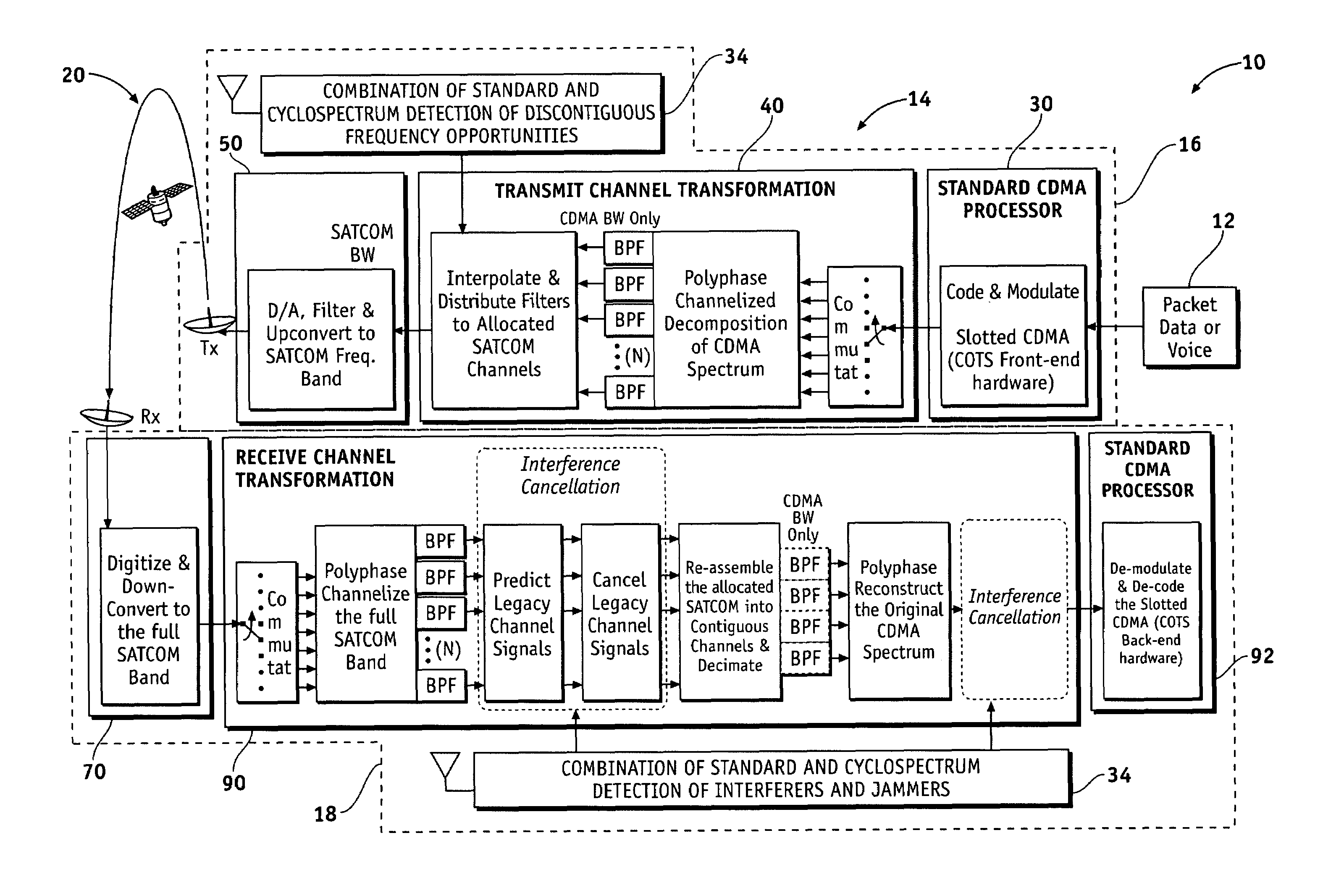
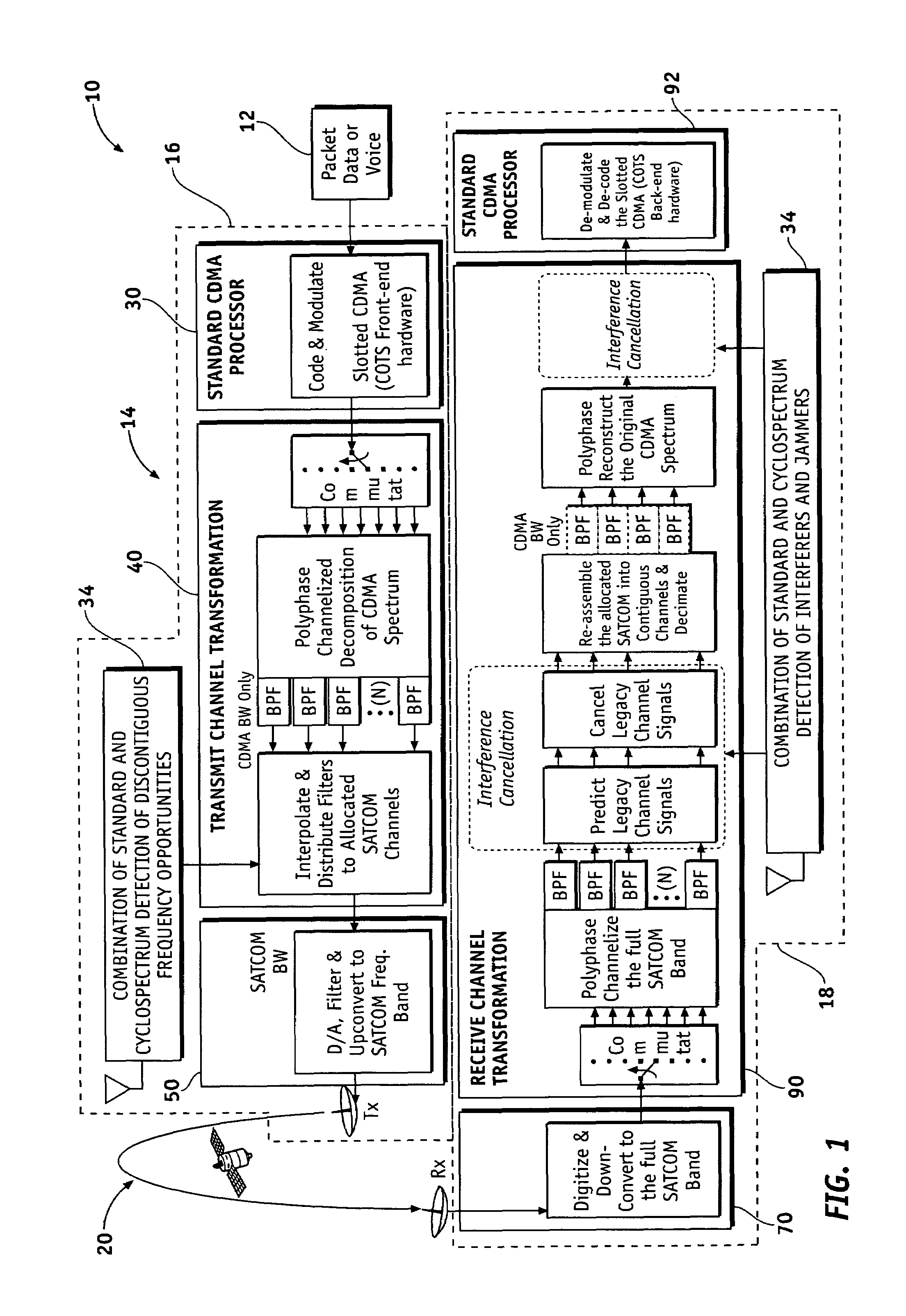
[0024]Although a spread spectrum radio is described hereinafter with regard to corresponding hardware that accomplishes signal processing functions, the spread spectrum radio may alternatively utilize software, such as found in software defined radios, that encompass applications, routines, or other software modules to accomplish signal processing functions. Those of skill in the relevant art will appreciate that other variations of hardware, software, or any combination thereof may be implemented to accomplish the same functions such as programmable microprocessors or controllers. Additionally, although a radio and a communication system are...


PUM


Abstract

An embodiment of a method for parameterizing an input signal includes non-linearly transforming the input signal, removing higher order terms by passing the input signal through a low pass filter to produce a linear combination of data symbols and DC components, solving for the DC components, separating a plurality of mixed baseband signals from the input signal, and coordinate transforming each of the separated signals from polar coordinates to Cartesian coordinates. An embodiment of a receiver includes a non-linear transform operator receiving a digitized input signal and adapted to produce a linear combination of data symbols, DC components, and carrier effects; a low-pass filter for removing higher order terms; a separator unit for separating the plurality of mixed baseband signals; and a coordinate transform for converting the separated signals from polar coordinates to Cartesian coordinates.

Description

FIELD OF THE INVENTION[0001]The present invention generally relates to spread spectrum communication, and more particularly relates to direct sequence spread spectrum communication using a polyphase channelization and a non-contiguous spectrum underlay based on standard and cyclostationary signal detection.BACKGROUND OF THE INVENTION[0002]Radio frequency (RF) spectrum is a scarce resource. In a cellular or personal communications systems environment, an increasing number of users need to be simultaneously serviced while also attempting to avoid interference among such users. One way to increase the number of simultaneous users on a given frequency band is code division multiple access (CDMA). CDMA refers to a form of multiplexing which allows numerous signals to occupy a single transmission channel thereby optimizing the use of available bandwidth. This technology is generally used in ultra-high-frequency (UHF) cellular telephone systems in the 800-MHz and 1.9-GHz bands.[0003]CDMA i...

Claims


Application Information

Patent Timeline
Patent Type & Authority Patents(United States)
IPC IPC(8): H04B1/00H04B1/707
CPCH04B1/7075H04B1/71H04B2201/70715
Inventor BERGSTROM, CHAD SCOTTMAALOULI, GHASSAN CHEHADECHUPRUN, JEFFERY SCOTT
Owner GENERAL DYNAMICS MISSION SYST INC
Why Eureka
Eureka Blog
Learn More