
Electrical terminal

a technology of electric terminals and terminals, which is applied in the direction of contact members penetrating/cutting insulation/cable strands, electrical appliances, fastening/insulating connecting parts, etc., can solve the problems of large cross section, large volume, and limited construction type of conventional terminals, and achieve simple and thus economical production. , the effect of simple manual opening of the clamping si

Inactive Publication Date: 2008-04-08
PHOENIX CONTACT GMBH & CO KG
View PDF16 Cites 32 Cited by
  • Summary
  • Abstract
  • Description
  • Claims
  • Application Information

AI Technical Summary

Benefits of technology

[0010]An object of embodiments of this invention is to provide an electrical terminal that enables simple manual opening of the clamping site, even with a strain-relief clamp designed for connection to leads with large cross section, which can be simply and thus economically produced.
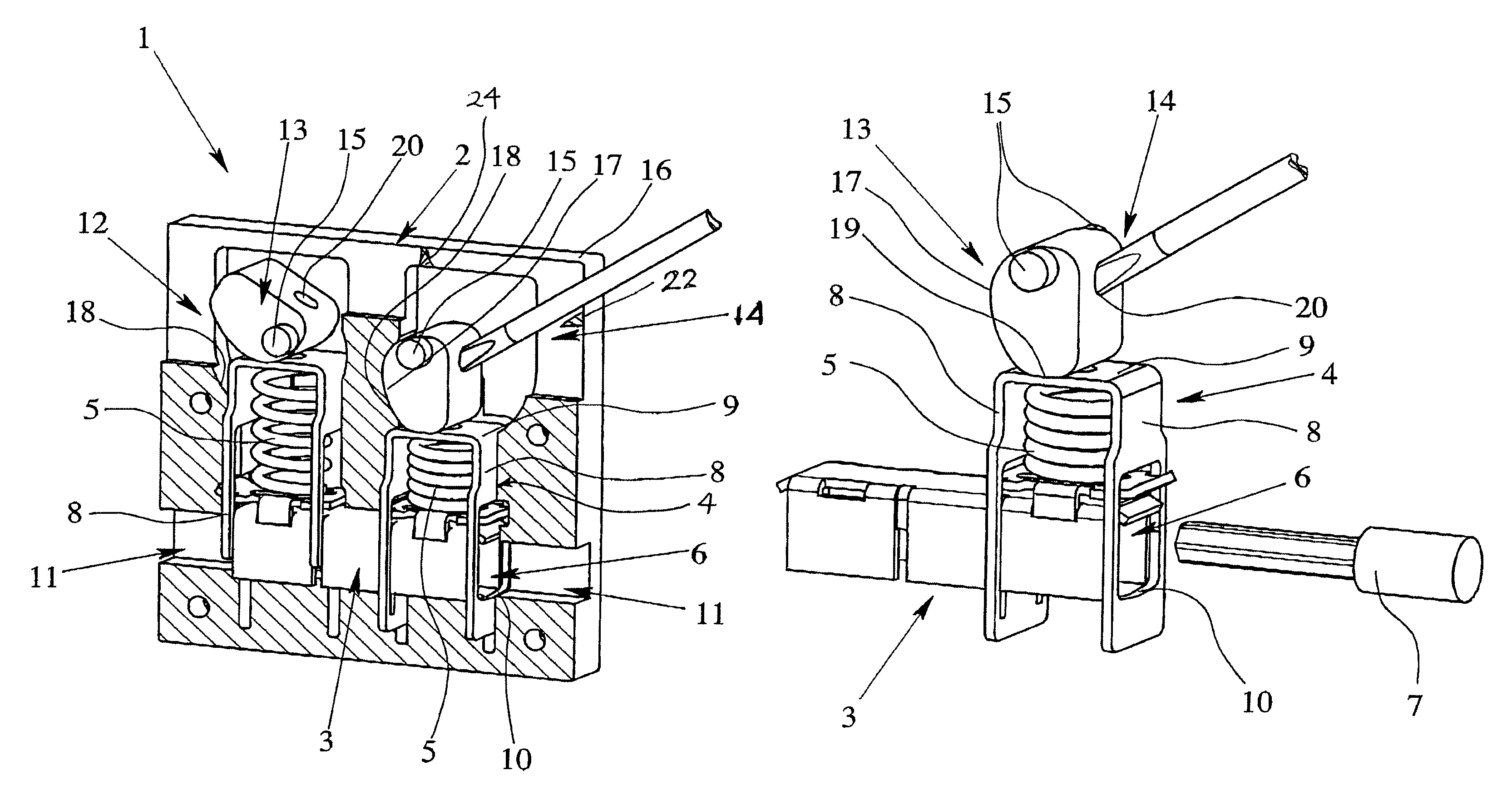
[0012]Because the actuating element is made as an actuating cam that is eccentrically supported in the insulating housing, the complex configuration of the inside of the housing for the rotation cylinder used in the prior art is eliminated. The movement of the actuating cam replaces the need for rotating the feed rotation cylinder used in the prior art. Moreover, opening of the clamping site is easily possible by pivoting the actuating cam so that the clamping site can be opened in a very time-saving manner. The force necessary for compressing the compression spring can be simply applied by the actuating cam being pivoted by means of an actuating tool. In this way, a relatively large lever arm is achieved so that the force to be expended even for a compression spring with high spring force is limited and thus can be easily applied by the electrician.
[0014]To pivot the actuating cam out of the first position into the second position and vice-versa, the actuating cam preferably has a receiver into which the tip of the actuating tool can be inserted. The receiver is located in the actuating cam such that an actuating tool that has been inserted through the actuation opening in the insulating housing can easily engage the receiver. Alternatively, to assist in positioning the receiver in the actuating cam, the latter can also have a grip section that the electrician can use manually or with a tool to pivot the actuating cam from one position into the other position.
[0015]The actuating cam can also be configured to be self-locking in its second position in which the strain-relief clamp connection is opened. This ensures that a strain-relief clamp connection that has been opened for insertion of the electric lead to be connected cannot unintentionally spring back into the closed state. The self-locking of the actuating cam in the second position can be easily implemented, for example, by moving the actuating cam in the second position where its vertex does not press on the U-shaped back of the strain-relief clamp, but rather is slightly pivoted beyond the vertex. Before the compression spring can relax again, by which the strain-relief clamp connection is closed, the compression spring must first be additionally compressed a small distance axially against its spring force.

Problems solved by technology

However, since high current terminals must also be manually actuated for opening the clamping sites against the respective clamping force of the clamping terminal, maximization of the type of construction of conventional terminals is limited, since lead cross sections starting with 50 mm2 often require excessive handling forces.
However, the configuration of the feed rotation cylinder and the inside thread in the insulating housing of the terminal are relatively complex and thus expensive to manufacture.

Method used


Image

  • Electrical terminal
  • Electrical terminal
  • Electrical terminal

Examples


Embodiment Construction

[0021]FIG. 1 shows an electrical terminal 1 with an insulating housing 2, a conductor bar 3 located in the insulating housing 2, and two strain-relief clamp connections. The two strain relief clamp connections each have a generally U-shaped strain-relief clamp 4 and a helical compression spring 5 located within the strain-relief clamp 4. As is especially apparent from FIGS. 2 and 3, the strain-relief clamp 4 has two clamping legs 8 that each have one through opening 6 for inserting an electric lead 7 to be electrically connected, and a U-shaped back 9 that connects the clamping legs 8 to one another. The conductor bar 3 is inserted into the through openings 6 of the strain-relief clamp 4 so that the through openings 6 surround the conductor bar 3.

[0022]The compression spring 5 is located between the U-shaped back 9 of the strain-relief clamp 4 and the conductor bar 3 such that the compression spring 5 pulls the lower edge 10 of the through opening 6 against the conductor bar 3, i.e....


PUM


Abstract

An electrical terminal includes an insulating housing, a conductor bar, strain-relief clamp connections and actuating elements located in the insulating housing for opening and closing the strain-relief clamp connections. The electrical terminal enables simple manual opening of the clamping site even when the strain-relief clamp connection is designed for leads with large cross section since the actuation element is made as an actuating cam that is eccentrically supported in the insulating housing. The actuating cam can be pivoted by an actuating tool out of a first position in which the strain-relief clamp connection is closed into a second position in which the strain-relief clamp connection is opened so that an electric lead can be inserted between the conductor bar and a through opening in the strain relief clamp connection.

Description

BACKGROUND OF THE INVENTION [0001]1. Field of the Invention[0002]The invention relates to an electrical terminal, especially a high current terminal, with a strain relief device.[0003]2. Description of Related Art[0004]Electrical terminals with contact elements made as tension springs, often called tension spring terminals, have been used for decades in industrial connection technology. In addition, electrical terminals with a screw-type terminal have been used for decades. The clamping principle for tension spring terminals is similar to that of screw technology. While in screw-type terminals a tension sleeve pulls the lead against a conductor bar by actuating the clamping screw, for a tension spring terminal this task can be assumed by a tension spring bent into a loop shape. The pretensioned tension spring is opened with an actuating tool, such as a screwdriver, so that the lead can be inserted into a through opening in the clamping leg of the tension spring into the terminal spa...

Claims


Application Information

Patent Timeline
Patent Type & Authority Patents(United States)
IPC IPC(8): H01R4/48
CPCH01R4/4872H01R4/5008H01R4/489H01R9/26
Inventor CAMINO, MANUELBRAND, JUERGENSCHULTE, HANS HILMAR
Owner PHOENIX CONTACT GMBH & CO KG
Learn More