
Dispensing device for drinks

a technology for dispensing devices and drinks, which is applied in the direction of liquid handling, instruments, packaged goods, etc., can solve the problems of practicability of conventional dispensing devices, and achieve the effect of uniform product quality

Inactive Publication Date: 2008-04-08
FRANKE TECH & TRADEMARK LTD
View PDF12 Cites 50 Cited by
  • Summary
  • Abstract
  • Description
  • Claims
  • Application Information

AI Technical Summary

Benefits of technology

[0008]The aim of the invention is that by means of a single filling mechanism, without additional work by hand, the various drinks can be put into the containers appropriate for each of them in such a way that a “falling height” can be set to be optimal for the drink in question. The result is not only to prevent soiling of the dispensing device by spray from the drink during filling; in addition, it can be ensured that because of the “gentle” filling a desired layering (foam on the cappuccino, the layers previously described in the case of latte macchiato) is achieved.
[0011]The identification means preferably comprises a filling-state sensor, by way of which to set a maximal filling state for the container, i.e. the amount of the foodstuff with which the container can be filled. In this way it can be ensured that an intentionally wrong operation to obtain multiple filling does not cause the container to overflow.
[0014]Alternatively or in addition the identification means comprises reading means to read information attached to the container, for example the above-mentioned magnetic strips or a barcode. Such arrangements can be very easily produced.
[0016]Preferably the filling mechanism comprises a container receptacle that is fixed in position and an adjustable dispensing region, so that the container can always be set down at the same height. The dispensing region is preferably connected to foodstuff-supply apparatus, such as storage vessels or the coffee-filter outflow etc., in such a way that a distance over which the foodstuff passes on the way from the supply means to an outlet into the open air is independent of the height of the filling mechanism. As a result, a uniform quality of the product can be ensured even for different filling heights.

Problems solved by technology

This is practically impossible with the conventional dispensing devices.

Method used


Image

  • Dispensing device for drinks
  • Dispensing device for drinks

Examples


Embodiment Construction

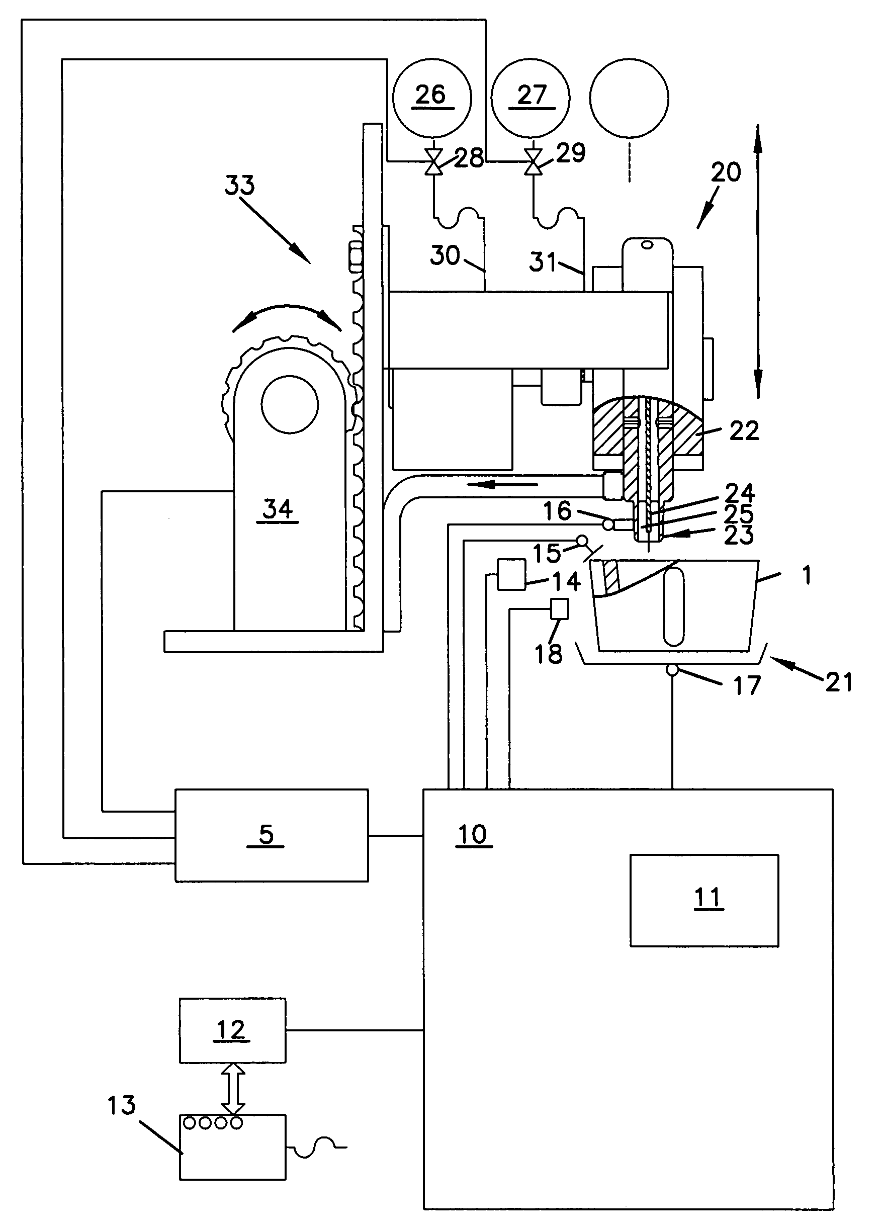
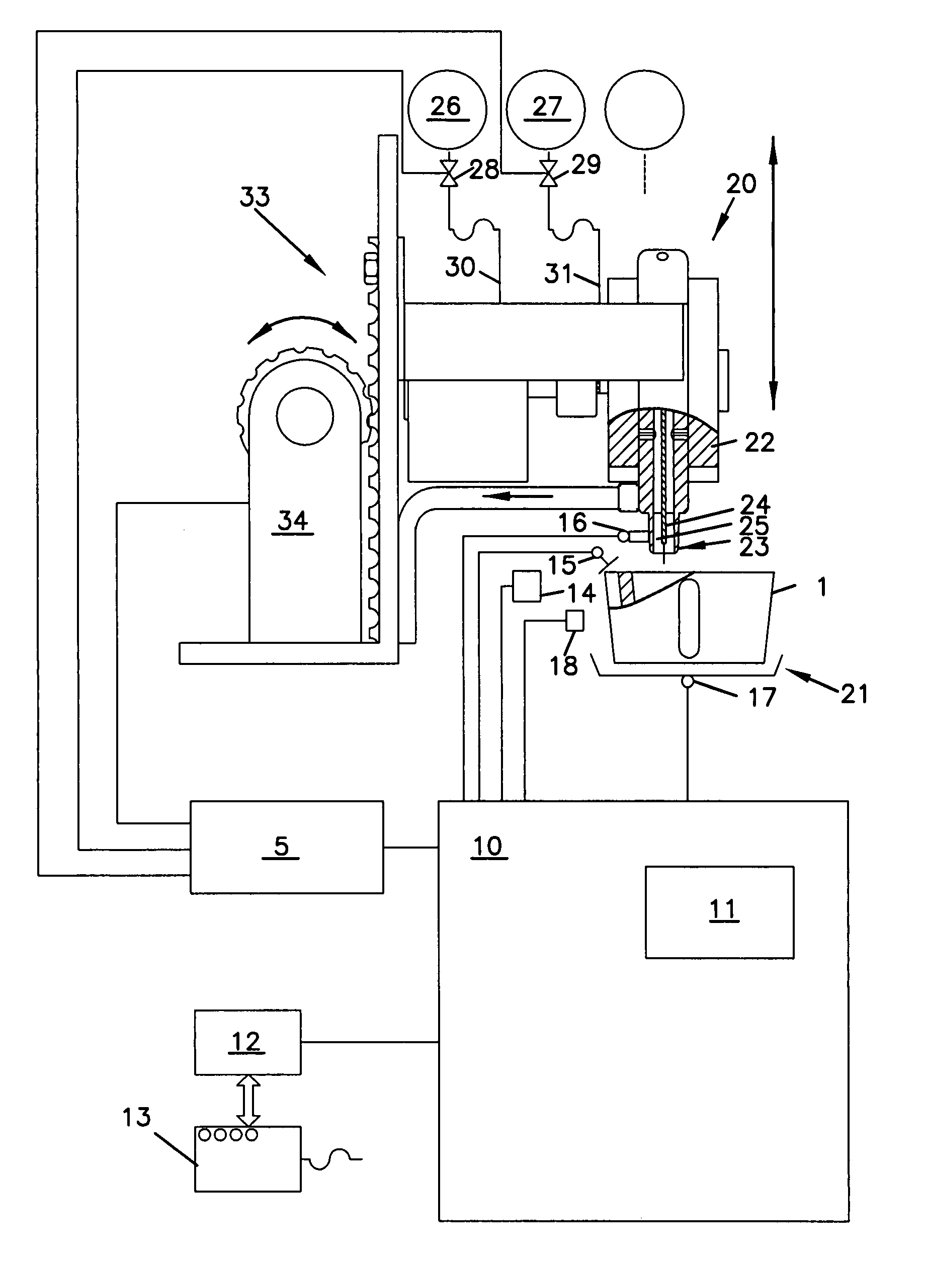
[0018]As shown in the drawing, a container 1, in the present case a cup, is set onto a container receptacle 21 of a filling mechanism 20. Above the cup 1 is an outlet 23, which comprises a first pipeline 24 and a second pipeline 25 that are united shortly ahead of the opening of the outlet 23. The outlet 23 is situated within a dispensing region 22 of the filling mechanism 20, which by way of a rack-and-pinion drive mechanism 33 with an adjustment gear 34 can be moved upward and downward (see double-headed arrow), so as to be lowered toward the container 1 or raised away from it. The first pipeline 24 and second pipeline 25, and hence the outlet 23, are connected by way of valves 28, 29 (and where appropriate, additional valves) as well as a first conduit 30 and a second conduit 31 (and where appropriate, additional conduits) to a first supply means 26 and a second supply means 27 (and where appropriate, additional supply means, as indicated in the drawing). The valves 28, 29 are co...


PUM

PropertyMeasurementUnit
vertical heightaaaaaaaaaa
heightaaaaaaaaaa
relative heightaaaaaaaaaa

Abstract

A dispensing device dispenses drinks or similar dosable liquid foodstuffs, especially coffee, milk, soft drinks or soups. The dispensing device includes an identification device for identifying a vertical height of a container for receiving the foodstuff and for emitting a height signal, a filling device which can be arranged in such a way that the height thereof can be adjusted in relation to the container, and a control device which sets the filling device to a pre-controllable filling level in relation to the container, on the basis of the height signal, before the foodstuff is introduced into the container. In this way, a container can be filled in an optimum manner without spilling.

Description

RELATED U.S. APPLICATIONS[0001]Not applicable.STATEMENT REGARDING FEDERALLY SPONSORED RESEARCH OR DEVELOPMENT[0002]Not applicable.REFERENCE TO MICROFICHE APPENDIX[0003]Not applicable.FIELD OF THE INVENTION[0004]The invention relates to a dispensing device for drinks or similar dosable liquid foodstuffs, in particular for coffee, milk, soft drinks or soups.BACKGROUND OF THE INVENTION[0005]Such dispensing devices, usually called “drinks vending machines”, have become customary not only in self-service restaurants or canteens, but are also used quite generally in gastronomy in order to reduce the number of service personnel. In order to dispense a large number of different drinks—espresso, cappuccino, latte macchiato and ordinary filter coffee are only some examples—a single dispensing device is used, with a filling mechanism capable of filling a container with drinks from various sources. Especially for supplying, e.g., cappuccino at an espresso machine, some work must be done by hand...

Claims


Application Information

Patent Timeline
Patent Type & Authority Patents(United States)
IPC IPC(8): B67C3/26A47J31/40A47J31/44G07F13/10B67D1/06B67D1/07B67D1/08
CPCA47J31/4482B67D1/06B67D1/08
Inventor GREIWE, HANSDIETERHERRMANN, RAINER
Owner FRANKE TECH & TRADEMARK LTD
Learn More