
Oven rack

a technology for oven racks and ovens, which is applied in the field of oven racks, can solve the problems of affecting the easy manipulation of food items, affecting the appearance of oven racks,

Inactive Publication Date: 2008-03-25
MAYTAG
View PDF21 Cites 15 Cited by
  • Summary
  • Abstract
  • Description
  • Claims
  • Application Information

AI Technical Summary

Benefits of technology

Enables easy manipulation of food items without disturbing their contents and facilitates the rack's movement by providing enhanced access and gripping points, reducing the risk of spills and damage during cooking operations.

Problems solved by technology

During a repositioning operation, the rack itself can interfere with the easy manipulation of the food item.
Without access to the bottom of the pie pan, it may become necessary to tilt the pie, which can result in spilling or otherwise disturbing the contents of the pie, or damage to the crust by gripping upper portions of the pie.
Given the thin profile of oven racks, grasping and shifting the oven rack out of the oven cavity can be difficult.
This problem is exacerbated by the need to wear oven mitts that generally do not allow a great deal of tactile manipulation.
Likewise, gripping internal portions of the pan is also difficult.
The size, thickness, and lack of mobility can make gripping inside portions of a pan, particularly with oven mitts, tricky and often times an awkward endeavor.

Method used


Image

  • Oven rack
  • Oven rack
  • Oven rack

Examples


second embodiment

[0025]In accordance with the invention, the food item access zone can be defined in various ways. In the present invention as represented in FIG. 3, a rack 129 is constructed in a manner similar to that described above with respect to rack 29. That is, rack 129 includes a frame portion 142 defined by front, rear and opposing side rods 144-147 preferably formed from bending a single metal bar. In addition, each side rod 146 and 147 is provided with a corresponding guide rail 150, 151 for slidably supporting rack 129 in oven cavity 5. Also shown in FIG. 3, rack 129 is provided with a cross rod 153 that increases the support capabilities of rack 129.

[0026]In accordance with this embodiment, front rod 144 of rack 129 is provided with first and second frontal segments 165 and 166, as well as first and second down-turned segments 168 and 169 that are interconnected by a vertically offset portion 174. As will be detailed more fully below, vertically offset portion 174 defines, in part, the...

third embodiment

[0028]the present invention illustrated in FIG. 4. This embodiment is quite similar to that of FIG. 3, while including a deeper or enlarged food item access zone. In this embodiment, a rack 229 includes a frame portion 242 defined by front, rear and opposing side rods 244-247. Each side rod 246, 247 is preferably formed with an upstanding section 250 spaced rearward of front rod 244. Upstanding section 250 is adapted to cooperate with structure (not labeled) formed on rails 21 to limit the degree of travel of rack 229 into and out of oven cavity 5. In general, this interaction between rack 229 and oven cavity 5 is known in the art and thus not considered part of the present invention so that further discussion thereof will not be made here. In a manner analogous to that described above with reference to racks 29 and 129, rack 229 is provided with a cross rod 253 that increases the overall carrying capacity of rack 229. Furthermore, front rod 244 of rack 229 includes first and second...


PUM


Abstract

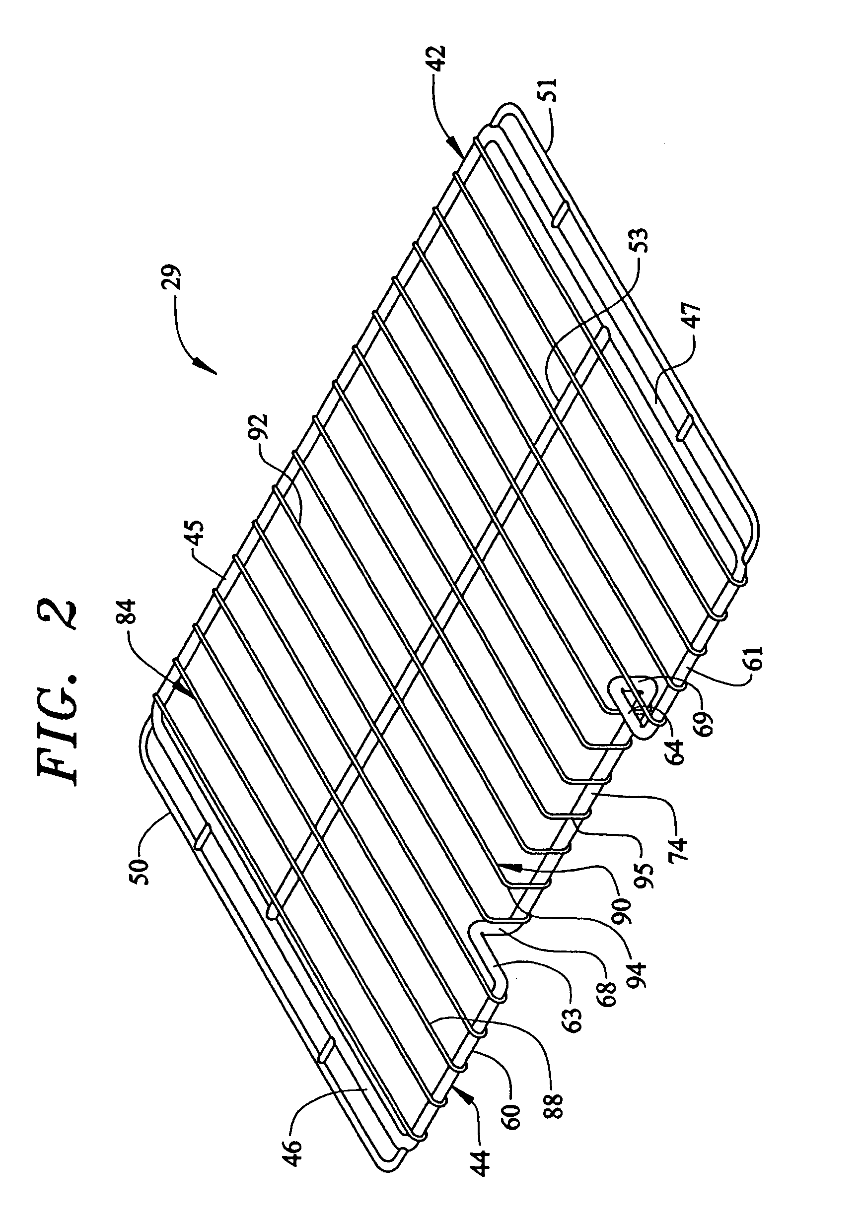
An oven rack for supporting food items to be cooked in a oven cavity of an appliance includes a frame portion and a support platform defined by a plurality of support members that establish a food item support zone and a food item access zone. The plurality of support members include substantially straight support members and offset or shaped support members. The offset support members, in combination with a vertically offset section of the frame portion, define the food item access zone which is vertically offset from the food item support zone so as to enable a consumer to access a bottom portion of a food item resting on the rack.

Description

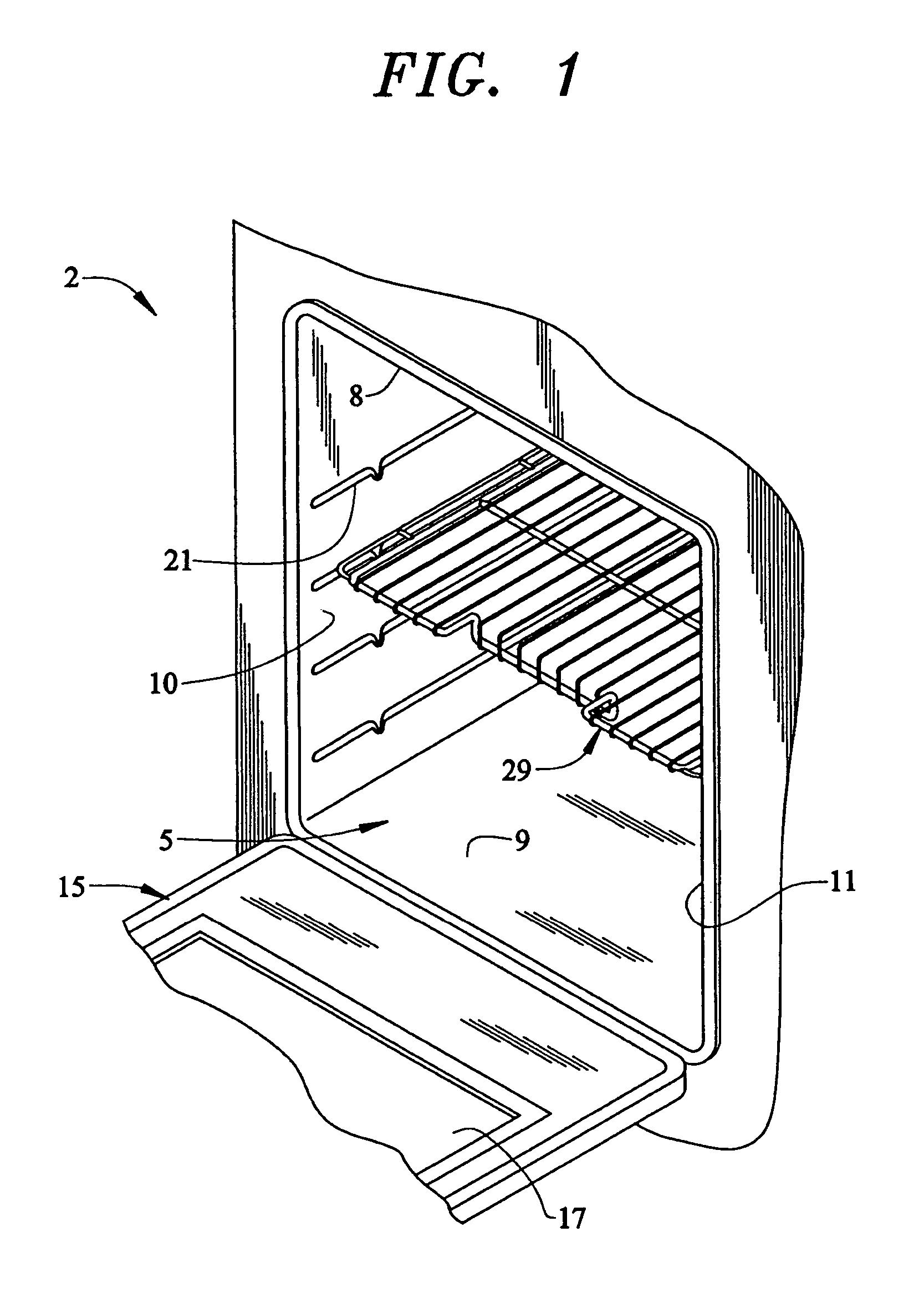
BACKGROUND OF THE INVENTION[0001]1. Field of the Invention[0002]The present invention pertains to the art of cooking and, more specifically, to a rack configured to enhance access and manipulation of products resting upon the rack within an oven cavity.[0003]2. Discussion of the Prior Art[0004]Typically, cooking appliances designed for household use are provided with one or more racks for supporting food items to be cooked within an oven cavity. The oven cavity itself is generally provided with a plurality of vertically spaced side wall rails for supporting respective lateral sides of the rack, while permitting the rack to be vertically adjusted. That is, the rack can slide along a selected set of support rails for movement into and out of the oven cavity, with the rack also being removable for cleaning or for repositioning at a different height.[0005]Oven racks are often of wire frame construction. More specifically, a typical oven rack would be defined by an outer wire frame and a...

Claims


Application Information

Patent Timeline
Patent Type & Authority Patents(United States)
IPC IPC(8): F24C15/16A47J9/00
CPCF24C15/16
Inventor FREESE, T. BRENTJACKOVIN, GARY B.SARGUNAM, ISSAC P.SHIN, INHO ANDY
Owner MAYTAG
Learn More