Abnormality detection apparatus for a power feed circuit
a technology of abnormality detection and power feed circuit, which is applied in the direction of relays, emergency protective arrangements for limiting excess voltage/current, pulse techniques, etc., can solve the problems of power transistors that cannot be protected to a satisfactory extent, so as to prevent burnout of power transistors and reduce overcurrent stress
- Summary
- Abstract
- Description
- Claims
- Application Information
AI Technical Summary
Benefits of technology
Problems solved by technology
Method used
Image
Examples
embodiment 1
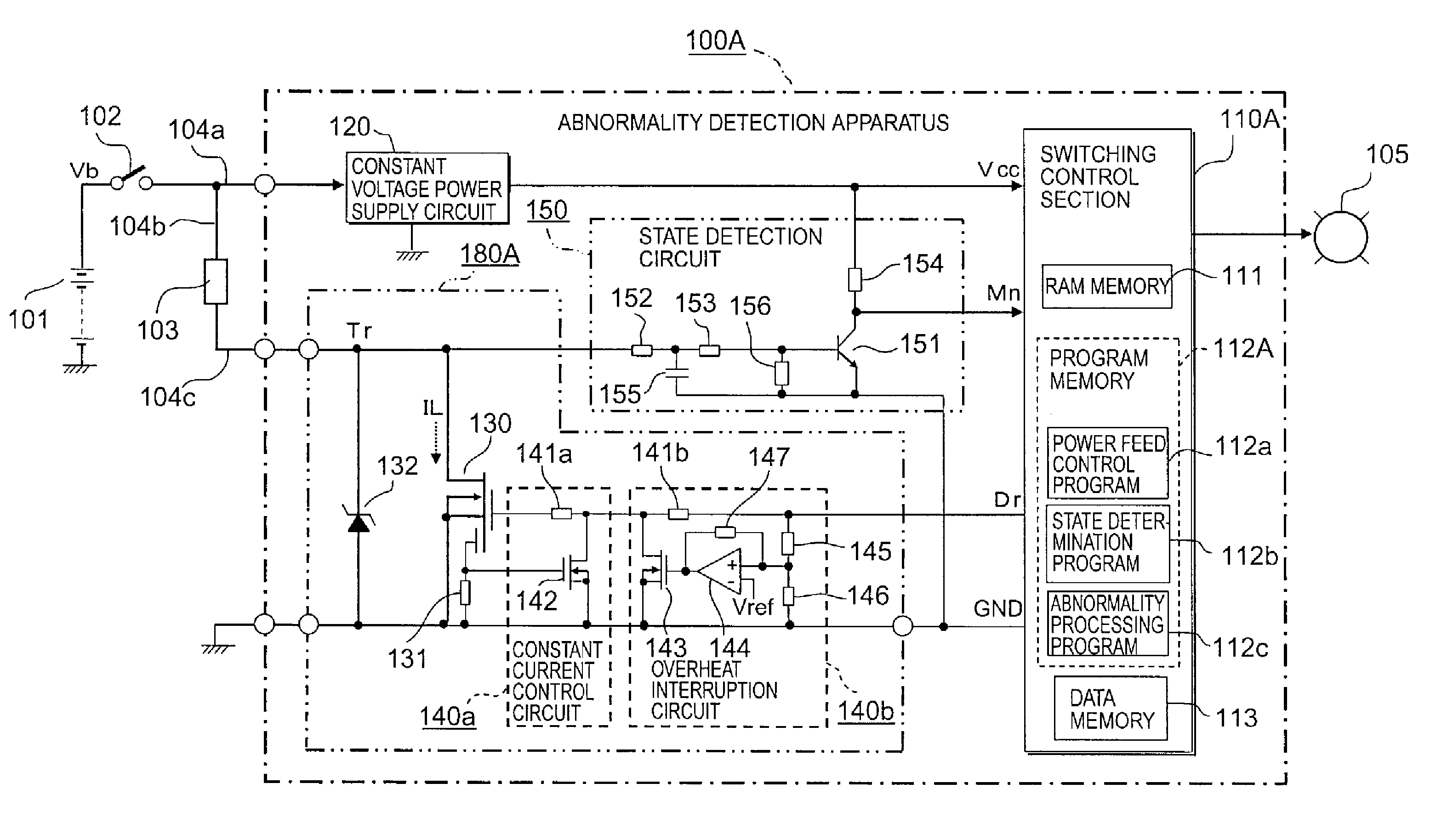
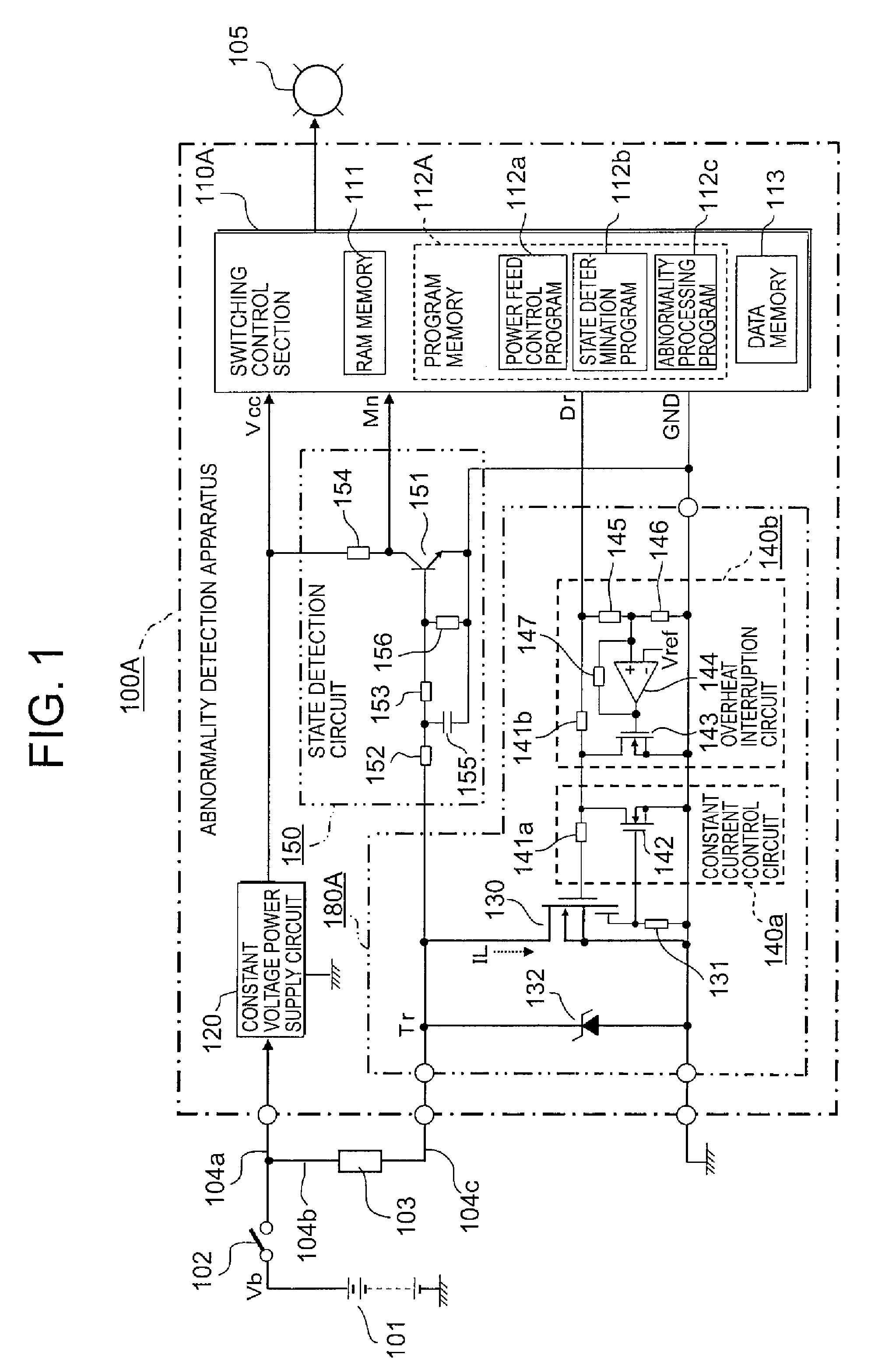
[0023]First, reference will be made to an abnormality detection apparatus for a power feed circuit according to a first embodiment of the present invention. FIG. 1 is a circuit block diagram that shows the overall configuration of the abnormality detection apparatus for a power feed circuit according to the first embodiment of the present invention.
[0024]In FIG. 1, the abnormality detection apparatus, generally designated at 100A, constitutes, in a concrete sense, an automotive engine control apparatus, and is fed power from a DC power supply 101 in the form of an on-board battery through a power switch 102 such as a key switch, etc., and a power supply line 104a.
[0025]In addition, an electric load 103 is composed, for example, of an electromagnetic coil for driving an electromagnetic valve for emission control in an automotive engine control unit, and is connected to the abnormality detection apparatus 100A. The electric load 103 is connected to the power supply line 104a through ...
embodiment 2
[0109]Although in the above-mentioned first embodiment (FIG. 1), the state detection circuit 150 is constructed separately from the power module 180A, a state detection circuit 170 may be built in a power module 180B, as shown in FIG. 6.
[0110]Hereinafter, reference will be made to an abnormality detection apparatus for a power feed circuit according to a second embodiment of the present invention while referring to FIG. 6.
[0111]FIG. 6 is a block diagram that illustrates the overall configuration of the abnormality detection apparatus for a power feed circuit according to the second embodiment of the present invention, wherein the same parts or components as those described above (see FIG. 1) are identified by the same symbols or by the same symbols with “B” affixed to their ends, while omitting a detailed explanation thereof.
[0112]In FIG. 6, the abnormality detection apparatus, generally designated at 100B, specifically constitutes a control unit of an automotive transmission, for e...
PUM
 Abstract
Description
Claims
Application Information
 - R&D
- Intellectual Property
- Life Sciences
- Materials
- Tech Scout
- Unparalleled Data Quality
- Higher Quality Content
- 60% Fewer Hallucinations
Browse by: Latest US Patents, China's latest patents, Technical Efficacy Thesaurus, Application Domain, Technology Topic, Popular Technical Reports.
© 2025 PatSnap. All rights reserved.Legal|Privacy policy|Modern Slavery Act Transparency Statement|Sitemap|About US| Contact US: help@patsnap.com


