
Alignment assembly for a prosthesis

a technology of alignment assembly and prosthesis, which is applied in the direction of prosthesis, coupling, rod connection, etc., can solve the problems of insufficient adjustment of known modular prosthetic components, inability to meet the needs of users over 220 pounds, and limited range of known devices

Active Publication Date: 2008-03-04
ENGINEERED SILICONE PRODS
View PDF9 Cites 45 Cited by
  • Summary
  • Abstract
  • Description
  • Claims
  • Application Information

AI Technical Summary

Benefits of technology

"The present invention provides an alignment assembly for a modular prosthesis that allows for selective linear and rotational / angular adjustability. The assembly includes a base, slidable components, and a locking mechanism for securely positioning the components in place. The dovetails slots and locking bars ensure stability and secure locking of the components. The technical effect of this invention is improved alignment and flexibility in the adjustability of a modular prosthesis."

Problems solved by technology

While significant advancements have been made in the field of lower limb prosthetics in recent years, all known devices are associated with certain limitations.
In this regard, known modular prosthetic components are generally not suitable for users exceeding 220 pounds.
Additionally, known modular prosthetic components do not provide sufficient adjustability to ensure proper alignment and ease of adjustment for higher weight patients.
Furthermore, known devices do not suitably provide a modular alignment assembly capable of connecting all known conventional modular components.

Method used


Image

  • Alignment assembly for a prosthesis
  • Alignment assembly for a prosthesis
  • Alignment assembly for a prosthesis

Examples


Embodiment Construction

[0014]The following description of various aspects of the present invention is merely exemplary in nature and is in no way intended to limit the invention, its application, or uses.

[0015]The present teaching provides an alignment assembly that can be installed into a modular prosthesis and can support body weights up to 425 pounds. In other instances, the alignment assembly of the present teachings can be used for pediatric applications for which dynamic loading will be significantly less.

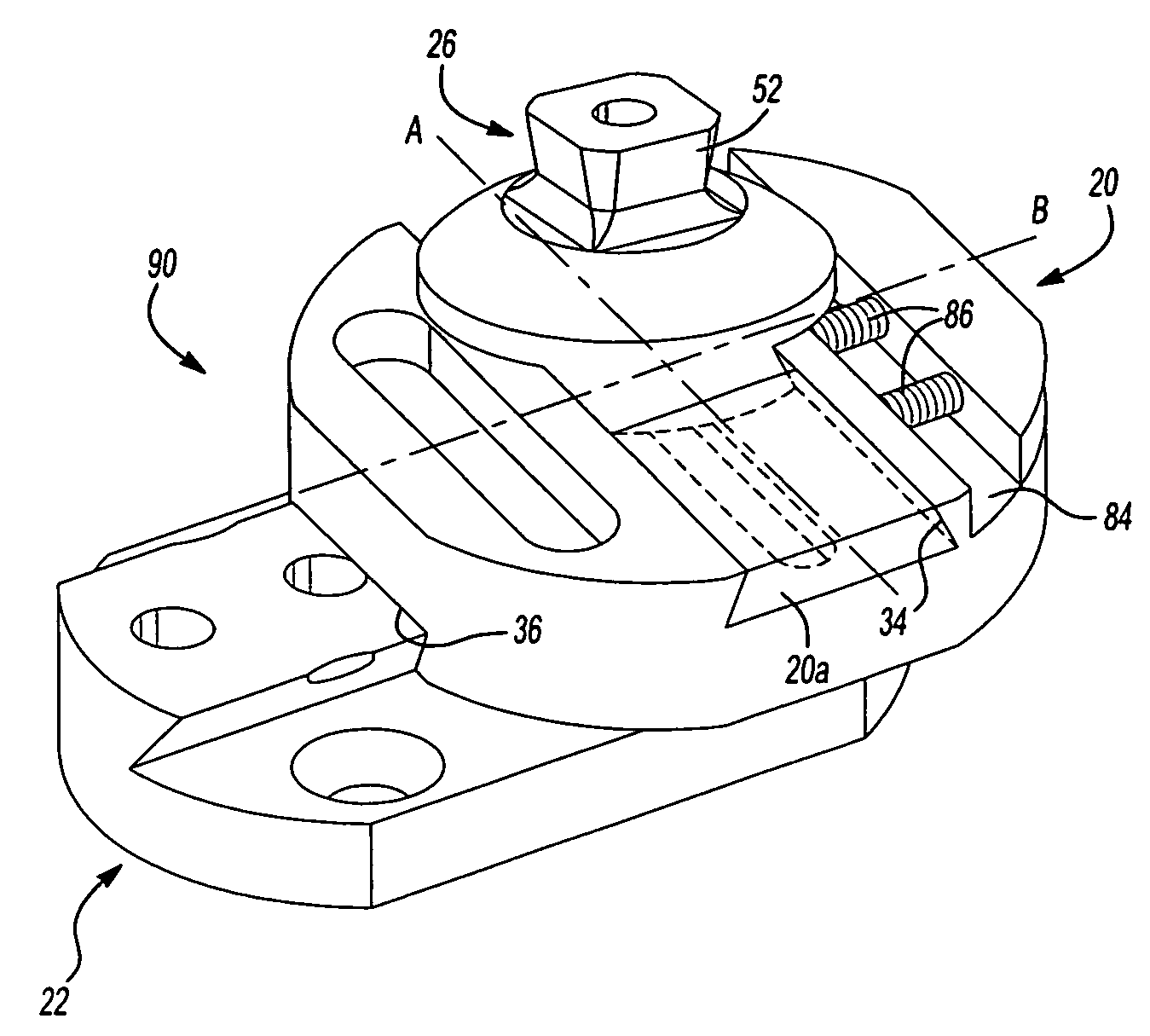
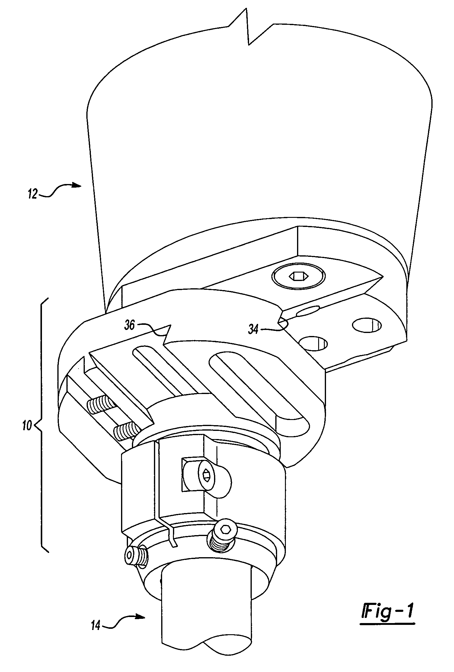
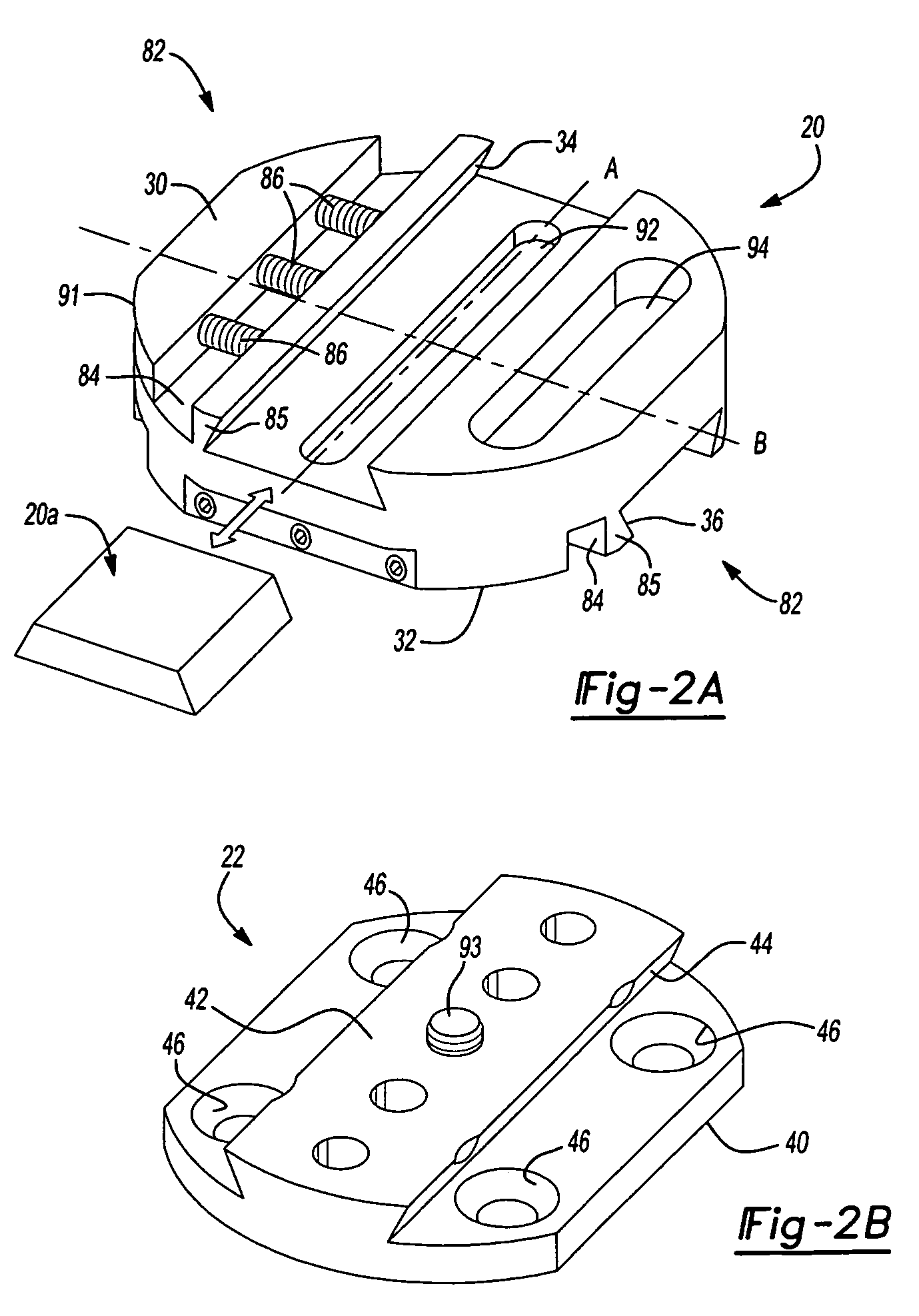
[0016]As described below in further detail, the modular alignment assembly can provide translation / linear adjustability in at least two directions. For example, the alignment assembly can provide adjustability in an anterior / posterior (A / P) direction and a medial / lateral direction (M / L). The M / L adjustability permits optimal alignment of a prosthetic socket or limb receptacle to a prosthetic foot and / or prosthetic knee for enhanced stability. The A / P adjustability permits appropriate weight transmi...


PUM


Abstract

An alignment assembly for a modular prosthesis. The alignment assembly includes a plurality of modular components that can be selectively connected to each other for providing selectively linear adjustability along first and second non-parallel axes, and rotational / angular adjustability about three orthogonal axes.

Description

CROSS-REFERENCE TO RELATED APPLICATIONS[0001]This application claims the benefit of U.S. Provisional Application No. 60 / 575,102, filed on May 27, 2004. The disclosure of the above application is incorporated herein by reference.INTRODUCTION[0002]Various prosthetic devices for the lower leg are known in the art.[0003]While significant advancements have been made in the field of lower limb prosthetics in recent years, all known devices are associated with certain limitations. In this regard, known modular prosthetic components are generally not suitable for users exceeding 220 pounds. Additionally, known modular prosthetic components do not provide sufficient adjustability to ensure proper alignment and ease of adjustment for higher weight patients. Furthermore, known devices do not suitably provide a modular alignment assembly capable of connecting all known conventional modular components.[0004]Accordingly, a need remains in the art for a prosthetic device which overcomes the limita...

Claims


Application Information

Patent Timeline
Patent Type & Authority Patents(United States)
IPC IPC(8): A61F2/80A61F2/00A61F2/50A61F2/62A61F2/76F16B7/00F16M11/04
CPCA61F2/76F16M11/04F16M11/041F16M11/2085F16M11/2092Y10T403/7094A61F2002/30387A61F2002/30434A61F2002/3051A61F2002/30512A61F2002/5023A61F2220/0025A61F2220/0033A61F2220/0041F16M2200/027A61F2002/30359A61F2002/30433A61F2002/30507F16B2200/30
Inventor HABERMAN, LOUIS JDALLOS, LASZLO E
Owner ENGINEERED SILICONE PRODS
Learn More