
Wireless communication network including directional and omni-directional communication links and related methods

a wireless communication network and omni-directional communication technology, applied in the field of communication, can solve the problems of complex scheduling time slots of wireless communication systems operating with directional antennas, mobile wireless communication systems, etc., and achieve the effect of mitiging the effects of interferen

Inactive Publication Date: 2008-02-19
STINGRAY IP SOLUTIONS LLC
View PDF11 Cites 57 Cited by
  • Summary
  • Abstract
  • Description
  • Claims
  • Application Information

AI Technical Summary

Benefits of technology

[0011]In view of the foregoing background, it is therefore an object of the present invention to schedule time slots and mitigate the effects of interference in a manner that is responsive to variations in communication link demands in a mobile wireless network.
[0013]That is, a directional communication link typically has a greater signal strength than an omni-directional communication transmitted at the same power level because the energy of the directional communication link is focused in one direction and not spread out. Thus, by requiring nodes to have a sufficient quality value for the omni-directional communication link before establishing the directional communication link, this provides a good indication that the directional communication link will also be of a desired quality level.

Problems solved by technology

Scheduling time slots for wireless communication systems operating with directional antennas, particularly when the wireless communication systems are mobile, is complex.

Method used


Image

  • Wireless communication network including directional and omni-directional communication links and related methods
  • Wireless communication network including directional and omni-directional communication links and related methods
  • Wireless communication network including directional and omni-directional communication links and related methods

Examples


Embodiment Construction

[0037]The present invention will now be described more fully hereinafter with reference to the accompanying drawings in which preferred embodiments of the invention are shown. This invention may, however, be embodied in many different forms and should not be construed as limited to the embodiments set forth herein. Rather, these embodiments are provided so that this disclosure will be thorough and complete, and will fully convey the scope of the invention to those skilled in the art. Like numbers refer to like elements throughout.

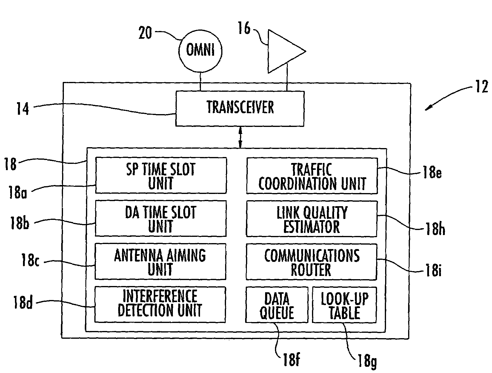
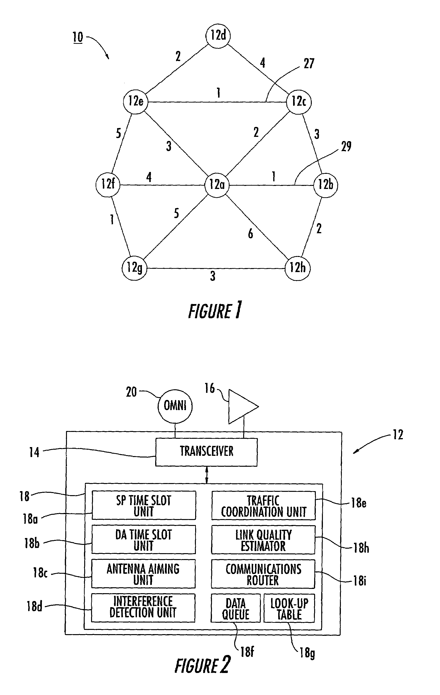
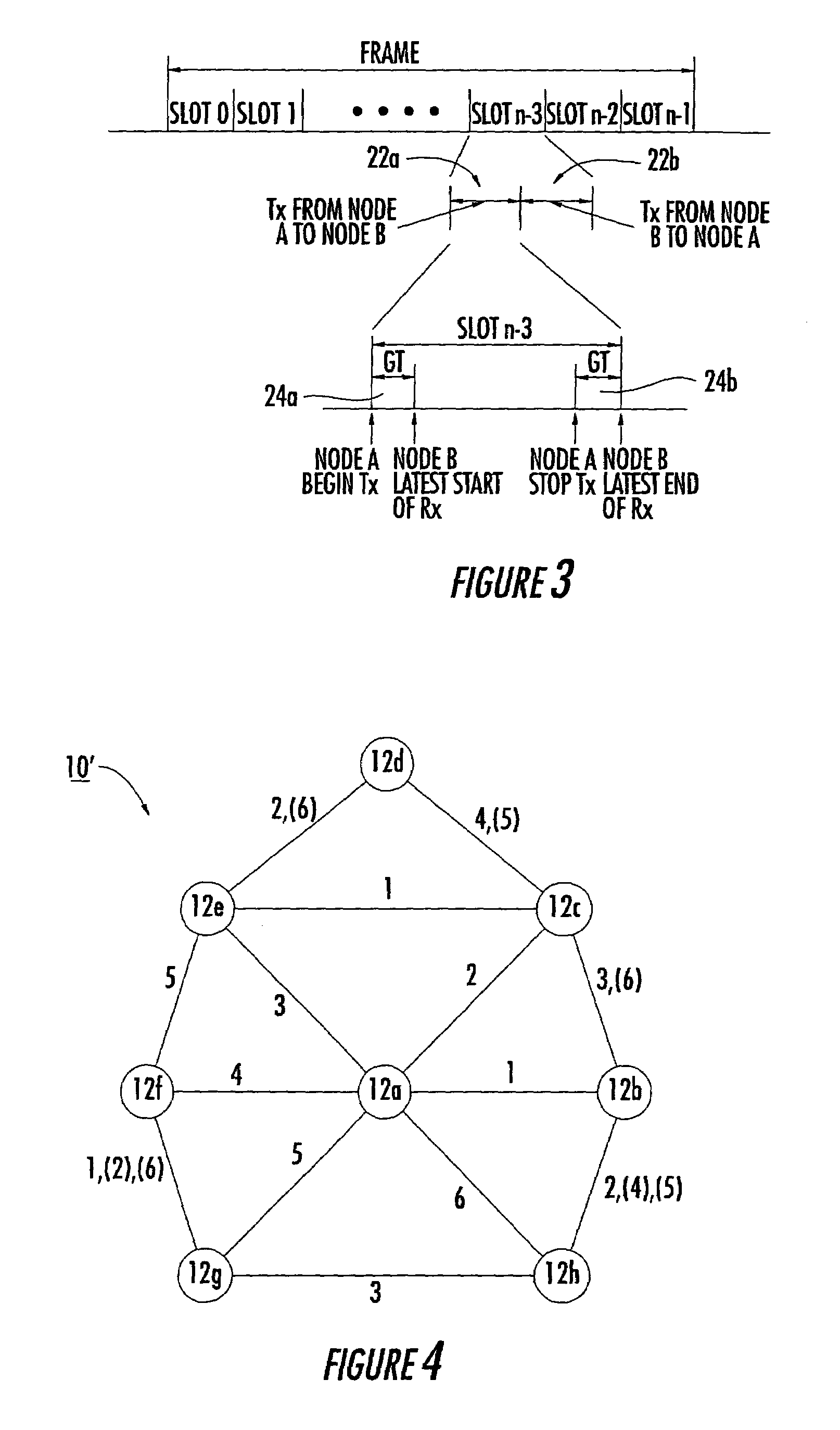
[0038]Referring initially to FIGS. 1-2, a wireless mobile communication network 10 comprises a plurality of wireless mobile nodes 12a-12h. Each mobile node 12a-12h comprises a transceiver 14, a directional antenna 16 connected to the transceiver, and a controller 18 connected to the transceiver.

[0039]The controller 18 includes a semi-permanent time slot unit 18a for scheduling a respective semi-permanent time slot for each time frame for establishing a comm...


PUM


Abstract

A wireless communication network may include a plurality of mobile nodes each including at least one wireless transceiver, a directional antenna and an omni-directional antenna connected to the at least one wireless transceiver, and a controller for controlling the at least one wireless transceiver. The controller may also be for controlling the at least one wireless transceiver, establishing an omni-directional communication link with another mobile node, and determining a link quality value for the omni-directional communication link. The controller may also establish a directional communication link with the other mobile node if the link quality value for the omni-directional communication link is greater than a quality threshold.

Description

RELATED APPLICATION[0001]This application is a continuation-in-part of application Ser. No. 10 / 043,457 filed Jan. 10, 2002 now U.S. Pat. No. 6,904,032, the entire disclosure of which is incorporated herein by reference.[0002]This invention was made with Government support under Contract Number N00014-96-C-2063 awarded by the Naval Research Laboratory. The Government has certain rights in this invention.FIELD OF THE INVENTION[0003]The present invention relates to the field of communications, and more particularly, to a network of mobile communication systems operating with directional antennas.BACKGROUND OF THE INVENTION[0004]Time division multiple access (TDMA) is one example of an access scheme used for establishing communication links between wireless mobile communication systems. Communication links between the wireless mobile communication systems are established within a series of time frames. Each time frame is divided into time slots, with each wireless mobile communication s...

Claims


Application Information

Patent Timeline
Patent Type & Authority Patents(United States)
IPC IPC(8): H04B7/212H04W72/54H04B7/04H04B7/26H04J3/16H04L1/00H04L1/20H04L12/28H04L12/56H04W16/14H04W16/28H04W74/04H04W76/02H04W84/18H04W88/06
CPCH04B7/0491H04L1/203H04J3/1694H04L1/0041H04L1/0061H04W72/085H04W76/025H04B7/2643H04W16/28H04W24/00H04W24/10H04W40/06H04W72/0446H04W72/10H04W74/04H04W76/02H04W84/18H04W76/15H04W76/10H04W72/542H04W72/56H04W40/12
Inventor CAIN, JOSEPH BIBB
Owner STINGRAY IP SOLUTIONS LLC
Learn More