
Method and system for an instant messenger home automation system interface using a home router

a technology of instant messenger and home automation, applied in the field of remote interaction, can solve the problems of increasing the difficulty of user learning to use the various systems, affecting the user's experience, and requiring operator training, so as to achieve the effect of easy understanding and convenient us

Inactive Publication Date: 2007-12-18
CISCO TECH INC
View PDF7 Cites 82 Cited by
  • Summary
  • Abstract
  • Description
  • Claims
  • Application Information

AI Technical Summary

Benefits of technology

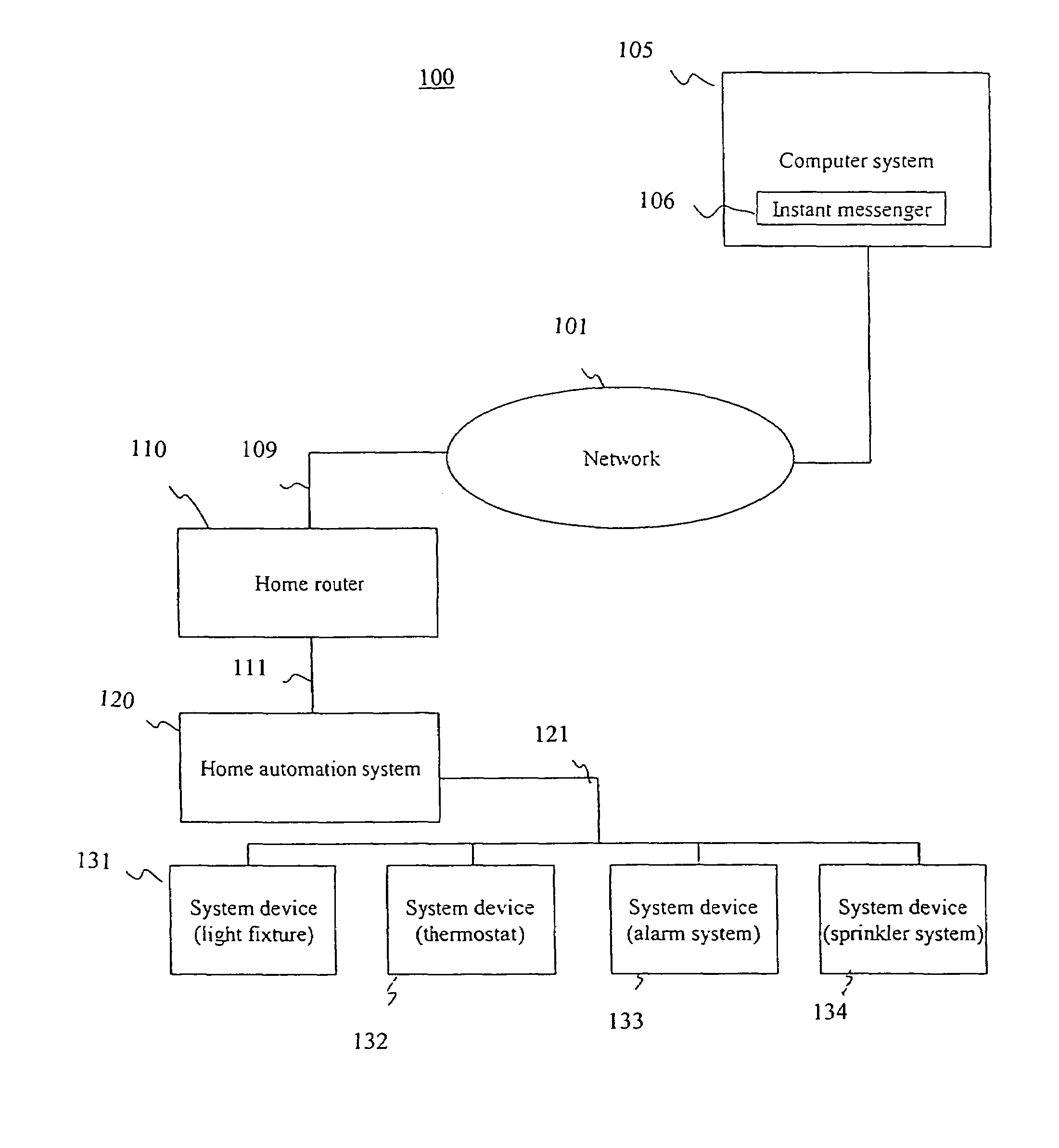
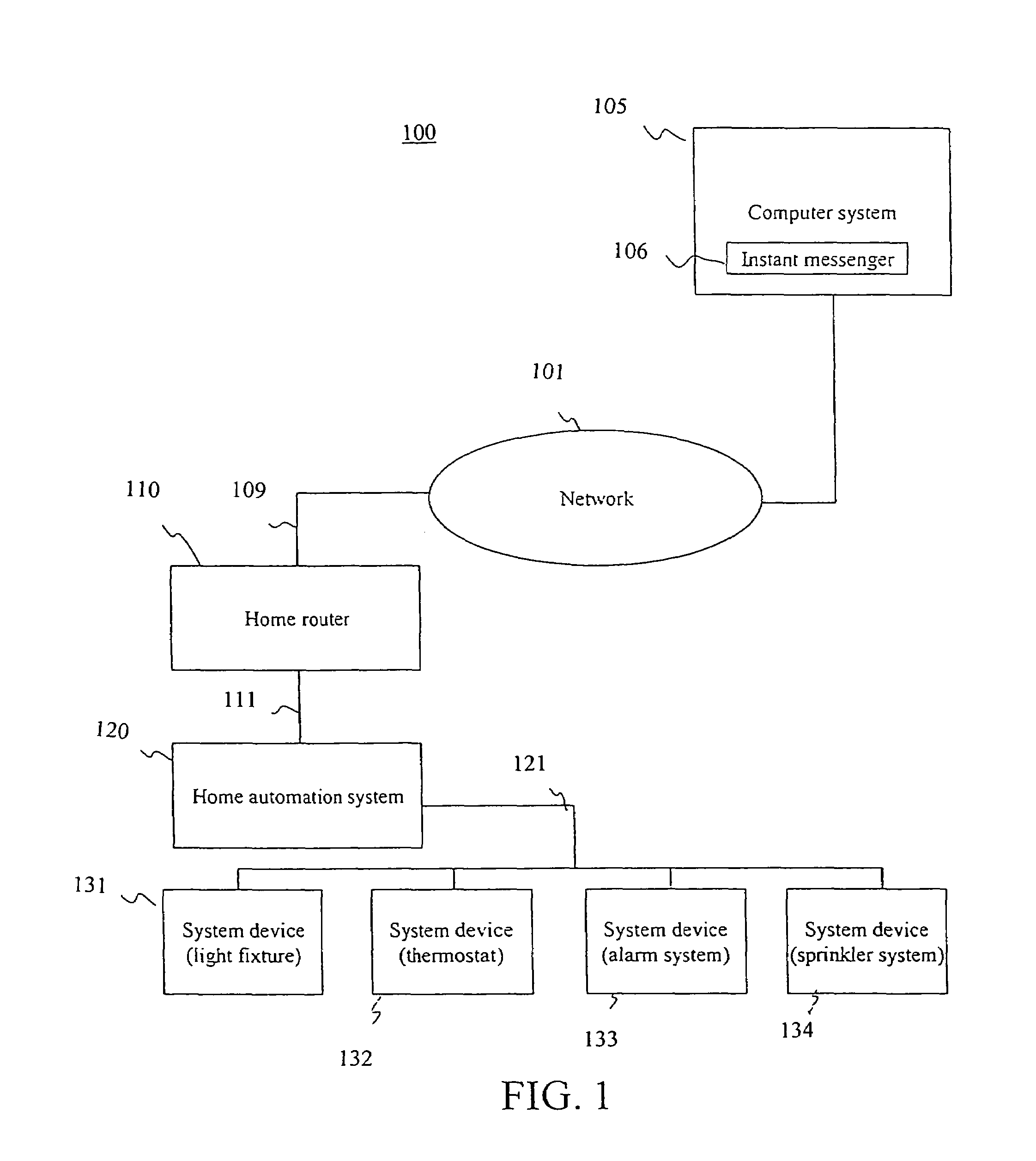
[0012]Embodiments of the present invention are directed towards a method and system for an instant messenger home automation system interface using a router. Embodiments of the present invention provide an easy to use and easy to understand interface for controlling an automation system. The interface system of the present invention is device independent with respect to different types of computer systems. The embodiments of the present invention function with standardized home automation system architectures. In addition, embodiments of the present invention provide for easy remote access and control of the functions of the automation system.
[0015]In this manner, the use of an instant messenger application and implementation of instant messenger functionality provides an easy to use and easy to understand interface for controlling an automation system. Instant messenger applications are device independent with respect to different types of computer systems (e.g., different desktop computer systems, different palmtop computer systems, cell phones, etc.). Additionally, the instant messenger functionality provides for easy remote access and control of the functions of the automation system.

Problems solved by technology

Reflecting the variety of appliances or devices that are to be controlled, user interfaces may range widely in complexity.
For example, a building control center may be sufficiently complicated to require training for the operator.
Unfortunately, the standard approach now commonly used is for each device or system in a given environment to be controlled according to a particular methodology which might differ dramatically from other systems.
By requiring the user to learn several methods of operating each system or set of devices in the environment, it is more difficult for the user to become familiar with the various systems and to take full advantage of all their features.
Another drawback associated with this standard approach is that the use of different interfaces may result in an increase in the amount of space taken up in the setting.
As a result, there may be a decrease in available wall space and a negative impact on the aesthetic quality of the setting.
The use of desktop computer systems or dedicated touch screen type displays in accordance with the prior art presents several problems.
In the case of touch screens, touchscreen hardware is relatively expensive and requires a somewhat substantial computer system platform to implement the control functionality (e.g., processor and memory elements).
In the case of desktop computer systems, the controller applications written for such computer systems tend to be complex.
Such controller applications are typically not portable among different types of machines (e.g., PC compatible computers, Macintosh computers, palmtop computers, etc.), and thus, control of the automation system depends upon having access to the desktop computer system.
An additional drawback is the fact that in order to control the automation system, the desktop computer system needs to be powered up.

Method used


Image

  • Method and system for an instant messenger home automation system interface using a home router
  • Method and system for an instant messenger home automation system interface using a home router
  • Method and system for an instant messenger home automation system interface using a home router

Examples


Embodiment Construction

[0021]Reference will now be made in detail to the embodiments of the invention, examples of which are illustrated in the accompanying drawings. While the invention will be described in conjunction with the preferred embodiments, it will be understood that they are not intended to limit the invention to these embodiments. On the contrary, the invention is intended to cover alternatives, modifications and equivalents, which may be included within the spirit and scope of the invention as defined by the appended claims. Furthermore, in the following detailed description of the present invention, numerous specific details are set forth in order to provide a thorough understanding of the present invention. However, it will be obvious to one of ordinary skill in the art that the present invention may be practiced without these specific details. In other instances, well known methods, procedures, components, and circuits have not been described in detail as not to unnecessarily obscure aspe...


PUM


Abstract

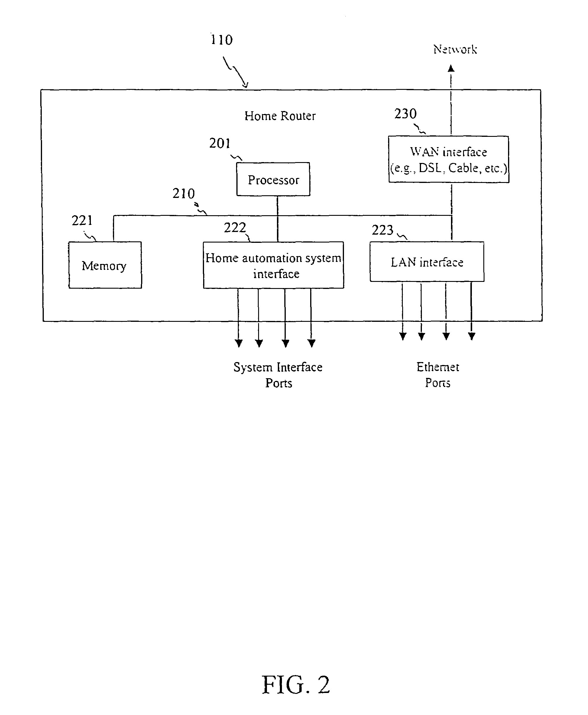
A method for interfacing with a home automation system using a router. The router receives control signals from an instant messenger application via a communications network. The communications network can be the Internet. The router then transmits the control signal to at least one appliance to control the appliance in accordance with the control signal. A reply to the control signal can be received from the appliance and the reply can be transmitted to the instant messenger application regarding a status of the appliance. The control signals can be transmitted among the appliances in accordance with a standardized home automation interface. The router can be configured to interface with a plurality of appliances via a home automation system interface unit. The router can also be configured to log onto an instant messenger server and function as an instant messenger client to receive control signals from a user.

Description

TECHNICAL FIELD[0001]This invention relates to the field of remote interaction with a variety of electronically controlled systems and appliances. More particularly, the present invention relates to an improved, easy to use, remote interface method particularly suited for use in residential or commercial automation systems.BACKGROUND ART[0002]In recent years, both the number and variety of electronic devices and appliances in use have increased dramatically. Lighting systems, personal computers (PCs), video tape recorders, compact disc (CD) players, stereo receivers, and televisions are but a few of the most common devices found n both residential and commercial settings. Even appliances which rely on non-electric power sources, such as gas burning furnaces, are usually controlled electronically.[0003]Reflecting the variety of devices now available, many different systems and devices are used to provide more centralized or automated control of the appliances found in the home and th...

Claims


Application Information

Patent Timeline
Patent Type & Authority Patents(United States)
IPC IPC(8): H04L12/28
CPCH04L12/2803H04L12/2818H04L12/2825H04L2012/285H04L12/581H04L51/04
Inventor SUE, JOHN AH
Owner CISCO TECH INC
Learn More