Coolant distributing means for an internal combustion engine

a technology of internal combustion engine and cooling system, which is applied in the direction of mechanical pressure/force control, fluid pressure control, instruments, etc., can solve the problems of cooling system liable to lower cooling performance, and achieve the effect of reducing the number of parts

Active Publication Date: 2007-12-18
NISSAN MOTOR CO LTD
View PDF7 Cites 1 Cited by
  • Summary
  • Abstract
  • Description
  • Claims
  • Application Information

AI Technical Summary

Benefits of technology

[0005]The present invention is worked out in view of the above-described problems in the prior art. It is an object of the present invention to provide a cooling system that is capable of removing the bubbles contained in the cooling water or coolant and returning the coolant without the bubbles into a coolant pumping means. The foregoing object is accomplished by a cooling system for performing the cooling of an internal combustion engine by means of circulating coolant. The cooling system includes a coolant pumping means for pumping the coolant; and a coolant returning means for removing bubbles included in the coolant and for returning the coolant without bubbles to the coolant pumping means. Accordingly, in this cooling system, the bubbles are prevented from entering the coolant pumping means, the efficiency of which is prevented from lowering, so that the cooling performance of the cooling system may be improved.
[0006]Another object of the present invention is to provide an internal combustion engine having a cooling system that is capable of removing bubbles contained in the coolant and returning the coolant without the bubbles into a coolant pumping means. Accordingly, in this internal combustion engine, the cooling performance of the engine may be improved.
[0008]In another embodied mode of the invention, the coolant returning means has a first path for returning the coolant to the coolant pumping means through a bubble removing portion capable of removing the bubbles, and a second path for returning the coolant to the coolant pumping means not through the bubble removing portion. In the second path is formed a bubble introducing portion capable of introducing the bubbles into the bubble removing portion through the first path. Accordingly, since the bubbles contained in the coolant flowing in the second path may be introduced through the bubble introducing portion into the bubble removing portion in the first path, the coolant containing bubbles may be well prevented from being returned into the coolant pumping means.
[0009]In a further embodied mode of the invention, the coolant returning means has a coolant distributing means comprising a feeding chamber for feeding the coolant after cooling the internal combustion engine into the first path and / or the second path; and a receiving chamber provided as a part of the second path under the feeding chamber for receiving the coolant fed into the second path from the feeding chamber and for returning the coolant into the coolant pumping means. The foregoing bubble introducing portion is a means for making the upper portion of the receiving chamber communicate with the feeding chamber. Accordingly, the bubbles within the coolant fed into the second path may be well removed by means of such a simple construction as making the upper portion of the receiving chamber communicate with the feeding chamber.
[0010]In a still further embodied mode of the invention, the coolant distributing means has a mating surface with the internal combustion engine; the feeding and the receiving chamber are divided by a partition formed as a part of the mating surface; and the bubble introducing portion is a notch formed in the partition. Accordingly, the bubble introducing portion may be realized in a simple construction such as a notch enabling a reduction in the numbers of parts.
[0011]In a still further embodied mode of the invention, the first path is provided with a heat radiating means for radiating the heat of the coolant and the bubble removing portion is formed in the heat radiating means. The bubble removing portion is formed as a cap in the existing radiator, so that it is possible to reduce the numbers of parts.

Problems solved by technology

As a result, air drawing occurs in the water pump and thereby the cooling system is liable to lower the cooling performance.

Method used


Image

  • Coolant distributing means for an internal combustion engine
  • Coolant distributing means for an internal combustion engine
  • Coolant distributing means for an internal combustion engine

Examples


Embodiment Construction

[0018]Hereinafter, an embodiment of the present invention will be described with reference to the drawings.

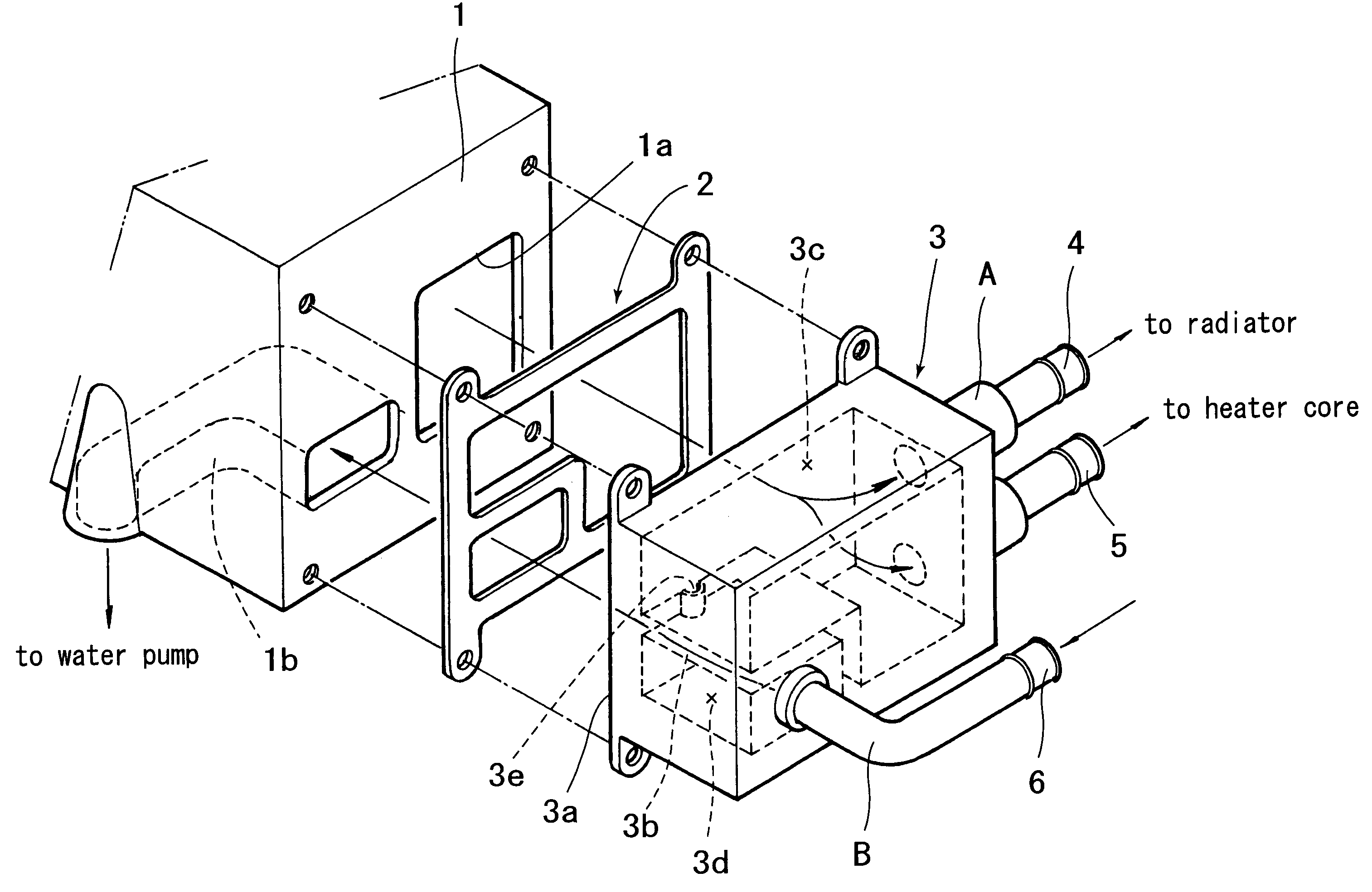
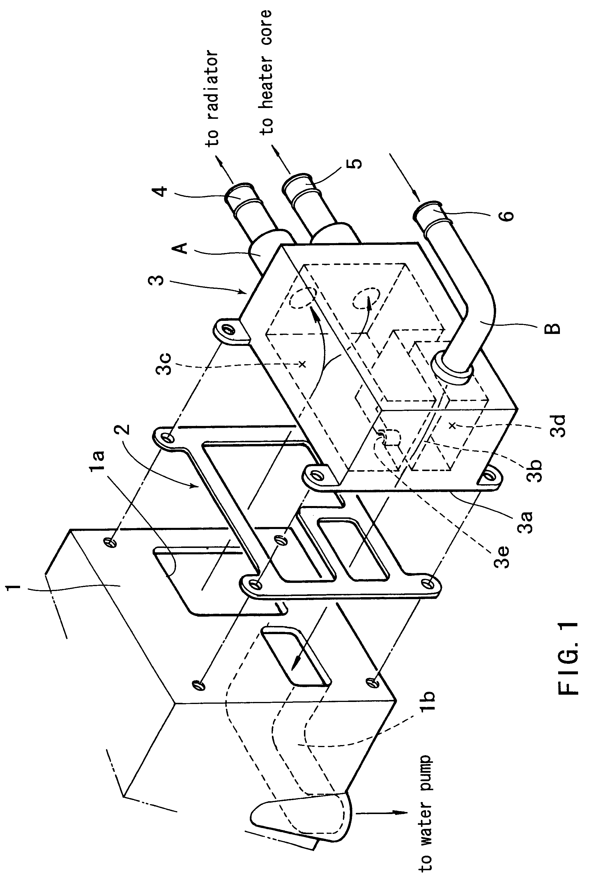
[0019]Referring to FIG. 1, FIG. 2 and FIG. 3, in the side surface of a cylinder head 1 constructing an internal combustion engine is provided an outlet 1a for coolant used to cool the interior of the internal combustion engine. Also, in the inside of the cylinder head 1 is formed a suction passage 1b to return the coolant into a water pump (coolant pumping means, not shown).

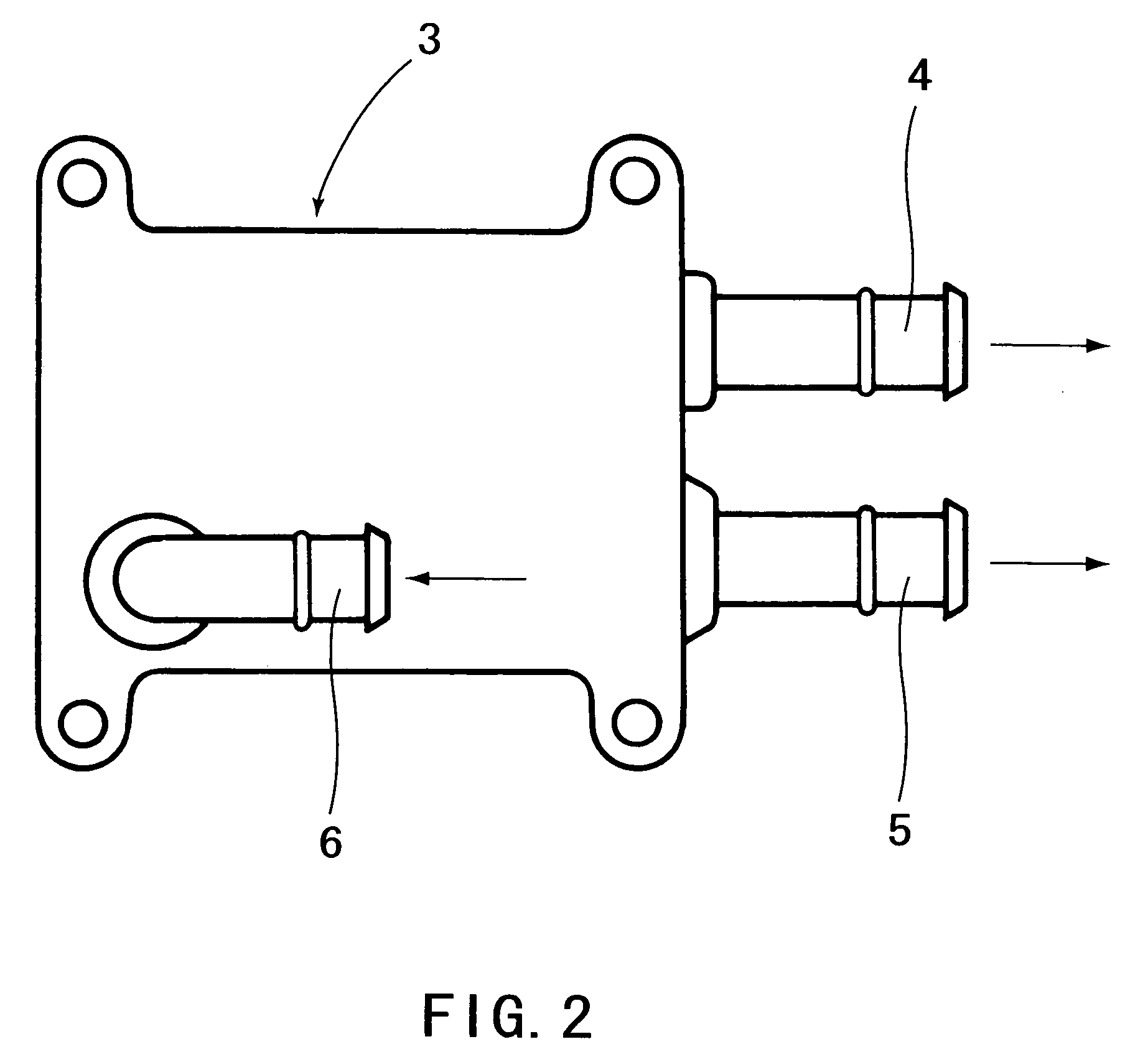
[0020]On the side surface of the cylinder head 1 is mounted a water outlet 3 (coolant distributing means) through a gasket 2 by means of bolts.

[0021]This water outlet (coolant distributing means) 3 has a mating surface 3a mating with the side surface of the cylinder head 1 through the gasket 2. In the interior of the water outlet 3 a feeding chamber 3c and a receiving chamber 3d are provided and respectively positioned above and below a partition 3b interposed therebetween. The upper portion of this receivin...


PUM


Abstract

A cooling system for an internal combustion engine in which bubbles are not transferred to the water pump, and thereby the efficiency of the water pump is maintained. The interior of a water outlet mounted on a cylinder head is divided by a partition wall to form a feeding chamber to feed the coolant introduced from the cylinder head to a first path provided with a radiator, and a receiving chamber forming a second path to receive the coolant returned from a heater core. Between the receiving chamber and the feeding chamber is a channel making one or both chambers communicate with the other. As a result, bubbles in the coolant running through the second path are introduced into the feeding chamber through the channel and removed from the radiator.

Description

FIELD OF THE INVENTION[0001]The present invention relates to a cooling system and an internal combustion engine provided with this cooling system.BACKGROUND OF THE INVENTION[0002]One known arrangement of the cooling system of this type is to perform cooling by circulating the coolant through the cylinder head and cylinder block by means of a water pump driven by the internal combustion engine, as disclosed in the following non-patent document 1, for example. In this cooling system, the coolant after cooling the cylinder head and cylinder block is returned to the water pump through a radiator and a heater, etc. The returned coolant is supplied again to the cylinder head and cylinder block through the water pump.[0003]Non-patent document 1: Service Manual HONDA ACCORD Section: Chassis Maintenance (2002, 10) Page 5-147, 5-156[0004]In such a cooling system, however, when the cylinder head and cylinder block are cooled, part of the coolant is vaporized and the produced bubbles are transf...

Claims


Application Information

Patent Timeline
Patent Type & Authority Patents(United States)
IPC IPC(8): F01P9/02
CPCF01P11/028F01P11/0285F01P2060/08
Inventor HADA, MASATOSHIICHIHARA, TAKAYOSHI
Owner NISSAN MOTOR CO LTD
Why Eureka
Try Eureka