Lateral control mechanism for an axle beam suspension system

a technology of lateral control mechanism and axle beam, which is applied in the direction of interconnection system, resilient suspension, vehicle components, etc., can solve the problems of lateral shift in suspension geometry, vehicle shake and vibrate, and inability to accommodate suitable length track bars in some vehicles

Active Publication Date: 2007-11-27
FCA US
View PDF1 Cites 22 Cited by
  • Summary
  • Abstract
  • Description
  • Claims
  • Application Information

AI Technical Summary

Problems solved by technology

However, a suitable length track bar cannot be accommodated in some vehicles, which have packaging constraints and / or lack attaching structures.
Short track bars are used in such cases, however the shortened length results in a lateral shift in the suspension geometry.
This causes the vehicle to shake and vibrate when the wheel on the axle jounces and rebounds.
In addition, the lateral shift caused by the shortened track bar affects the wheel, tire, and coil spring packaging envelopes.
This concentrated load degrades the noise levels and harshness measurements of the ride.

Method used


Image

  • Lateral control mechanism for an axle beam suspension system
  • Lateral control mechanism for an axle beam suspension system
  • Lateral control mechanism for an axle beam suspension system

Examples


Embodiment Construction

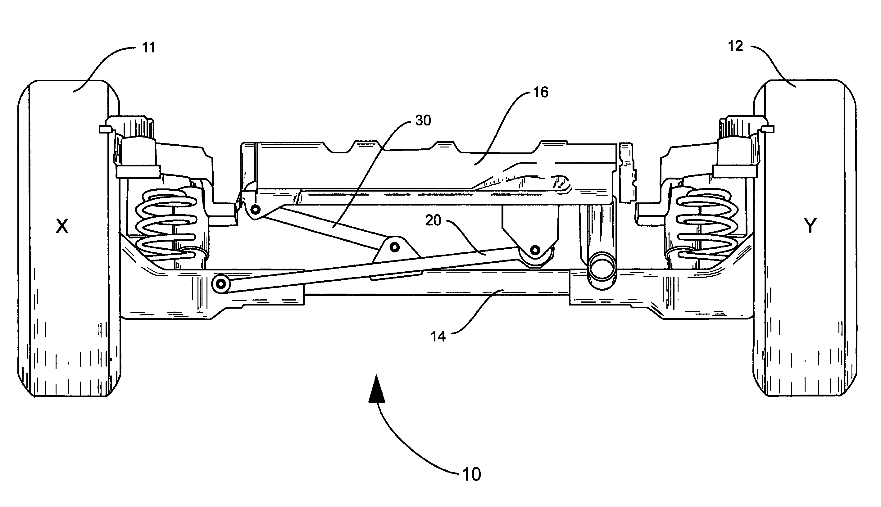
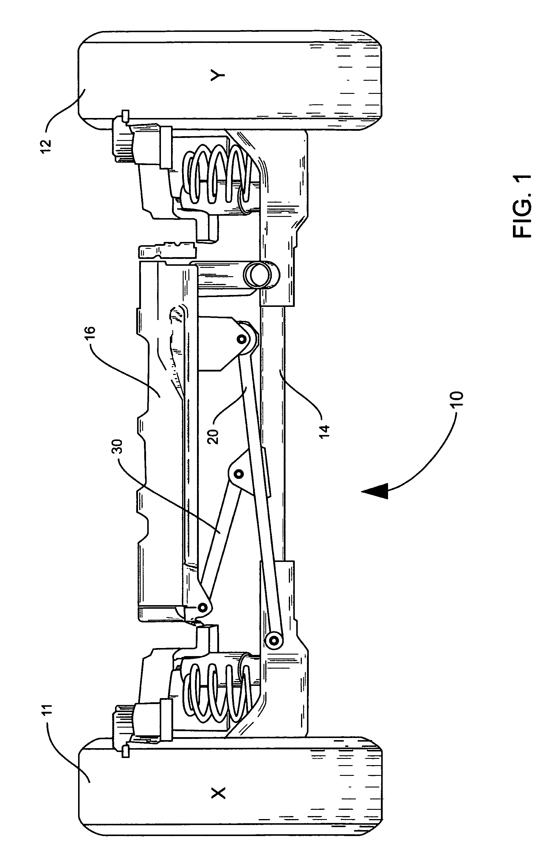
[0016]FIG. 1 illustrates a rear view of an axle beam suspension system 10 in a mobile vehicle (not shown) in accordance with the present invention. The axle beam suspension system 10 includes a main vehicle body 16, of which only a bottom portion is illustrated, an axle 14 movably attached to the main vehicle body 16, a track bar 20, and a control bar 30. The axle 14 connects a first wheel 11 and a second wheel 12 at opposing ends. The first wheel 11 and the second wheel 12 include the appropriate tires, brakes and any other components required for the mobile vehicle as known in the art. Point X and point Y approximately indicate the rearward projections of the points where axle 14 is attached to first wheel 11 and second wheel 12, respectively.

[0017]The track bar 20 is about half the width of the main vehicle body 16. The width of the complete main vehicle body is generally about the distance between the first wheel 11 and the second wheel 12. The illustrated bottom portion of the ...


PUM


Abstract

An axle beam suspension system for a mobile vehicle, the system includes a main vehicle body, an axle attached to the main vehicle body, a control bar, and a track bar. The track bar includes a controlling connection portion. A first end of the track bar is attached at a lateral attachment to a lateral joint connection portion of the main vehicle body. A second end of the track bar is attached at a pivot attachment to a pivot joint portion on the axle. The control bar has a first end attached at a control attachment to a control joint connection portion of the main vehicle body and a second end attached at a fourth attachment to the controlling connection portion of the track bar. A lateral portion of an axle-pivoting-movement is transferred into lateral movement of the axle beam suspension system.

Description

FIELD OF THE INVENTION[0001]This invention relates generally to axle beam suspension systems. In particular, the invention relates to transferring the lateral movement of a wheel on a pivoting axle to the axle beam suspension system.BACKGROUND OF THE INVENTION[0002]Conventional mobile vehicles are typically equipped with suspension systems to manage the impact of forces and disturbances on the roadway so the vehicle occupants experience a comfortable ride. Axle beam suspension systems operate to reduce the vehicle roll and the shake of the occupants of the mobile vehicle.[0003]Axle beam suspension systems in which a track bar extends across the width of the region between wheels opposably positioned at the ends of the axle generally provide a suspension geometry without lateral shift. However, a suitable length track bar cannot be accommodated in some vehicles, which have packaging constraints and / or lack attaching structures. Short track bars are used in such cases, however the sho...

Claims


Application Information

Patent Timeline
Patent Type & Authority Patents(United States)
IPC IPC(8): B60G21/05
CPCB60G9/00B60G11/14B60G2204/421B60G2200/3415B60G2200/30
Inventor JOHNSON, JAMES JOPEIKO, ALEXANDREWILLIAMS, RONALDABBADI, MOHAMED
Owner FCA US
Why Eureka
Try Eureka