
Self-locked hinge device

a self-locking, hinge technology, applied in door/window fittings, multi-purpose tools, construction, etc., can solve the problems of expensive automatic document feeder damage, ineffective reduction of mfp cost,

Inactive Publication Date: 2007-11-27
AVISION
View PDF11 Cites 17 Cited by
  • Summary
  • Abstract
  • Description
  • Claims
  • Application Information

AI Technical Summary

Benefits of technology

[0009]It is therefore an object of the invention to provide a self-locked hinge device capable of facilitating the assembling processes of a multi-function peripheral and effectively preventing the cover from falling down.
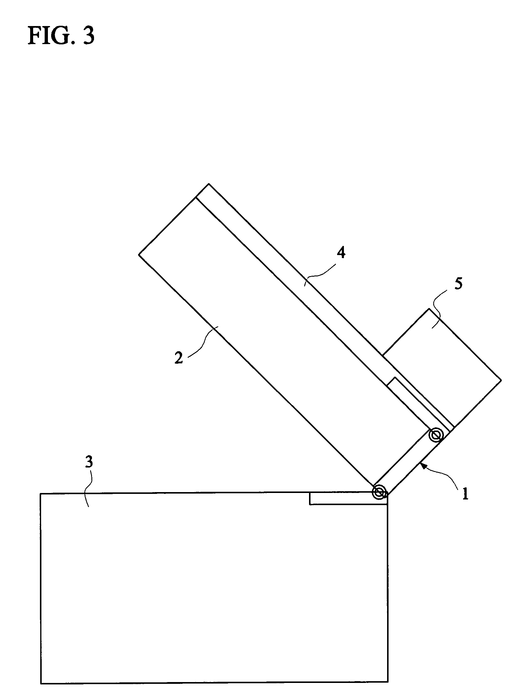
[0012]According to the above-mentioned structure, the user can lift up the cover and the scanning unit separately so as to place the sheet or document, replace the consumable material or overcome the paper jam. In addition, when the user lifts up the scanning unit, the cover is locked in order to prevent the cover from falling down, damaging or hurting someone.

Problems solved by technology

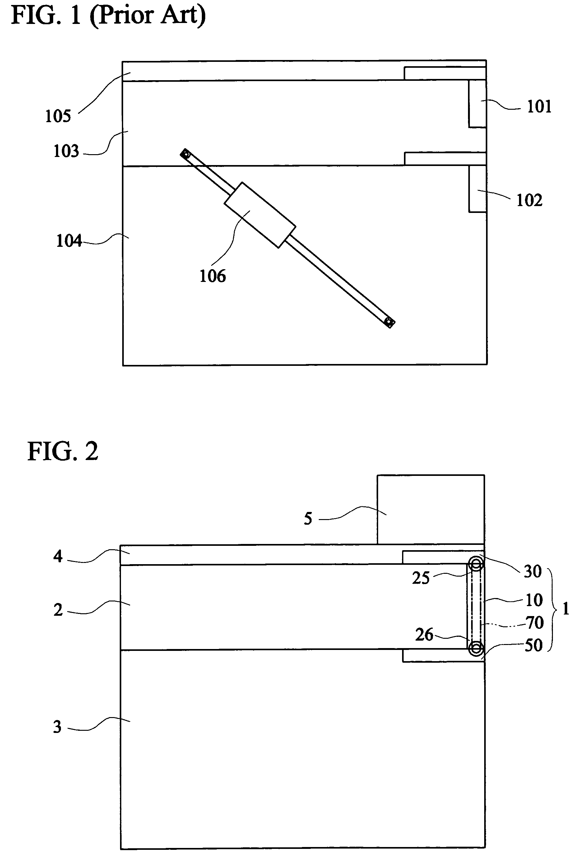
Because two hinges have to be mounted independently, the assembling processes are complicated, and thus the cost of the MFP cannot be effectively reduced.
If the cover 105 falls down owing to the lifting up of the scanning unit 103, the expensive automatic document feeder may be damaged.

Method used


Image

  • Self-locked hinge device
  • Self-locked hinge device
  • Self-locked hinge device

Examples


Embodiment Construction

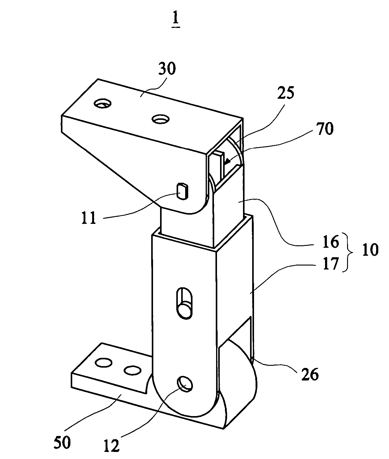
[0025]FIG. 2 is a schematic illustration showing a multi-function peripheral according to a preferred embodiment of the invention. FIG. 3 shows the state when the scanning unit of FIG. 2 is lifted up. FIG. 4 shows the state when the cover of FIG. 2 is lifted up. Referring to FIGS. 2 to 4, the multi-function peripheral includes a self-locked hinge device 1, a scanning unit 2, a printing unit 3, a cover 4 and an automatic document feeder 5. It is to be noted that the automatic document feeder 5 may be omitted in some conditions. The self-locked hinge device 1 includes a hinge body 10, a first mounting plate 30, a second mounting plate 50 and a locking mechanism 70. The hinge body 10 has a first end 25 and a second end 26. The first mounting plate 30 is hinged to the first end 25 and the second mounting plate 50 is hinged to the second end 26. The locking mechanism 70 locks the first mounting plate 30 and the hinge body 10 together such that the first mounting plate 30 cannot move rela...


PUM


Abstract

A self-locked hinge device includes a hinge body, a first mounting plate, a second mounting plate and a locking mechanism, The first mounting plate is hinged to a first end of the hinge body, and the second mounting plate is hinged to a second end of the hinge body. The locking mechanism is driven by the second mounting plate when the second mounting plate is moved and incapacitates the first mounting plate from moving relatively to the hinge body when the second mounting plate is rotated to a predetermined position relative to the hinge body. A multi-function peripheral using the self-locked hinge device is also provided.

Description

[0001]This Non-provisional application claims priority under 35 U.S.C. § 119(a) on Patent Application No. 092123667 filed in Taiwan on Aug. 27, 2003, the entire contents of which are hereby incorporated by reference.BACKGROUND OF THE INVENTION[0002]1. Field of the Invention[0003]The invention relates to a self-locked hinge device and a multi-function peripheral using the same, and more particularly to a self-locked hinge device with two integrated hinges and a multi-function peripheral using the same.[0004]2. Description of the Related Art[0005]The multi-function peripheral (MFP) is now very popular because it has the functions of scan, print, or even fax. In a conventional MFP, the printing unit is usually located below a scanning unit. The user has to replace the toner or ink cartridge with a new one after the toner or ink has been consumed in either a laser or ink-jet type printing unit. At this time, the user has to lift up the scanning unit so as to perform the replacement oper...

Claims


Application Information

Patent Timeline
Patent Type & Authority Patents(United States)
IPC IPC(8): E05D11/10E05D3/06H04N1/00
CPCH04N1/00543H04N1/00554E05D3/12H04N2201/0094Y10T16/547Y10T16/5518Y10T16/54095Y10T16/54052Y10T16/5478Y10T16/5407Y10T16/544Y10T16/5406Y10T16/54025Y10T16/5408
Inventor CHANG, YU-LUN
Owner AVISION
Learn More