
Small motor

a small motor and motor housing technology, applied in the direction of dynamo-electric machines, magnetic circuit shapes/forms/construction, supports/enclosements/casings, etc., can solve the problems of difficult the inability to downsize the stepping motor, so as to prevent the occurrence of striking noise, the effect of reducing the size of the motor and reducing the size of the stepping motor

Inactive Publication Date: 2007-10-23
SANKYO SEIKI MFG CO LTD
View PDF7 Cites 3 Cited by
  • Summary
  • Abstract
  • Description
  • Claims
  • Application Information

AI Technical Summary

Benefits of technology

[0014]In view of the problems described above, it is a primary object and advantage of the present invention to provide a motor which is capable of attaining the downsizing of the motor while preventing the occurrence of striking noise in the radial direction which may be generated between the rotor shaft and the bearing member.
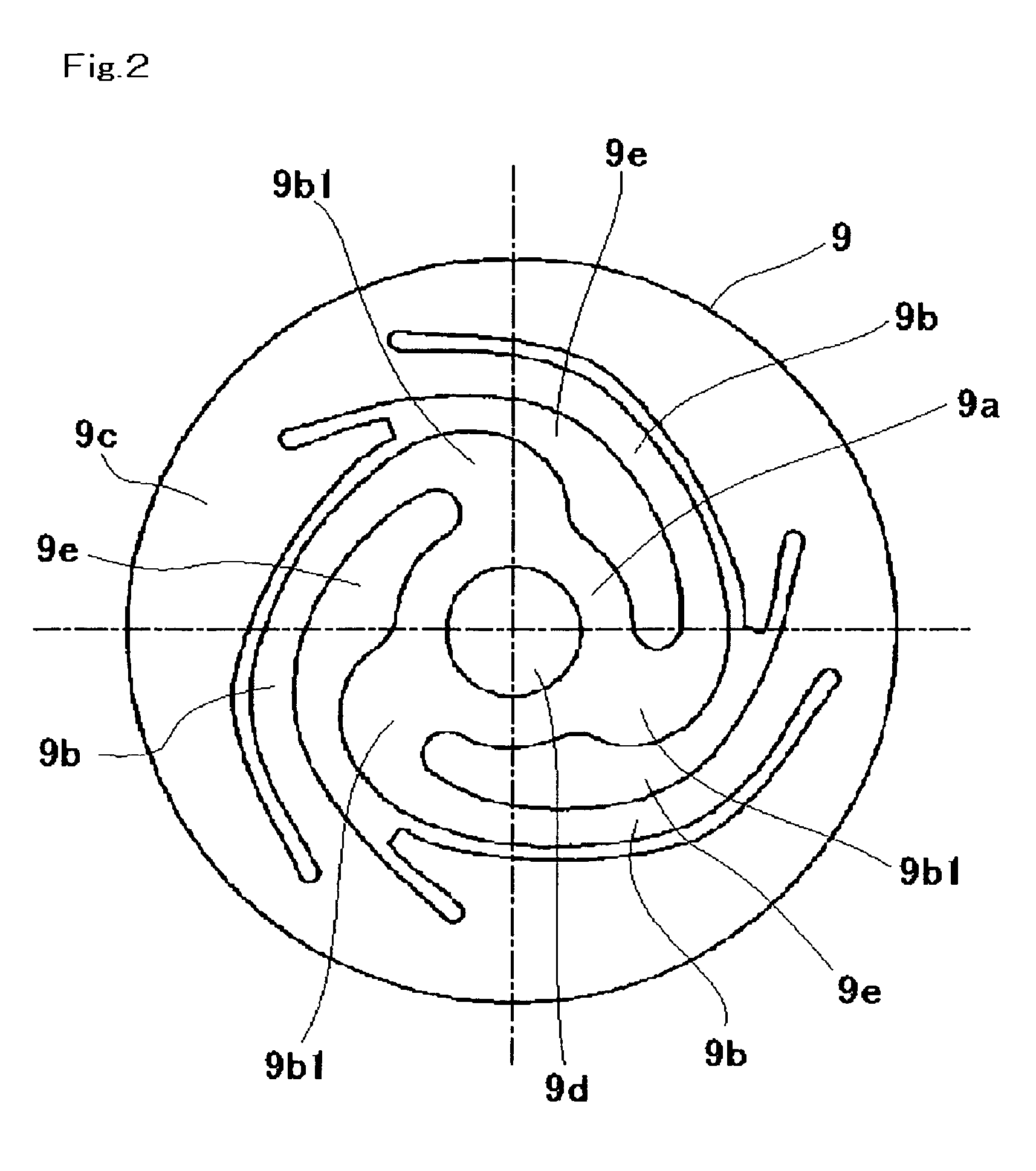
[0015]In order to achieve the above object and advantage, according to an embodiment of the present invention, there is provided a small motor including a rotor including a rotor shaft and a permanent magnet which is fixed to the outer periphery of the rotor shaft, a stator having pole teeth which face the permanent magnet in a radial direction, a bearing member which supports a base end on an opposite-to-output end of the rotor shaft in the radial direction and a thrust direction, and a bearing holding member which holds the bearing member. The bearing holding member is formed in a thin plate-shaped elastic member and includes a bearing holding part which holds the bearing member, at least an arm part which is extended outward from the bearing holding part in the radial direction in a spiral manner, and an outer peripheral part which is connected to the arm part at a position outward in the radial direction of the bearing holding part and which is fixed to the stator.
[0016]In accordance with an embodiment of the present invention, the motor is provided with a bearing member which supports a base end on an opposite-to-output end of the rotor shaft in the radial direction and a thrust direction and a bearing holding member which holds the bearing member. Therefore, the occurrence of striking noise in a bearing gap space formed between the bearing member and the rotor shaft can be prevented. Further, since the bearing holding member is formed in a thin plate-shaped elastic member, the downsizing of a motor can be attained even when the bearing member is held by the bearing holding member.
[0017]In accordance with an embodiment of the present invention, the bearing holding member is provided with a bearing holding part which holds the bearing member, at least an arm part which is extended outward from the bearing holding part in the radial direction in a spiral manner, and an outer peripheral part which is connected to the arm part at a position outward in the radial direction of the bearing holding part and which is fixed to the stator. Since the arm part is extended from the bearing holding part in a spiral manner and then connected to the outer peripheral part, the length of the arm part can be ensured and thus the bending amount of the arm part can be attained. Therefore, the bearing member which is held by the bearing holding part can be movably held in the thrust direction even when the bearing holding member is formed of a thin plate-shaped elastic member. Accordingly, the occurrence of noise generated in the thrust direction can be prevented.
[0018]In accordance with an embodiment of the present invention, the bearing holding member is preferably provided with three or more arm parts. According to the construction described above, since the bearing holding part is supported by three or more arm parts, the support strength for the bearing member can be ensured in the thrust direction and the radial direction even when the arm part is extended from the bearing holding part in a spiral manner such that the length of the arm part is ensured to obtain the bending amount of the arm part.
[0019]In accordance with an embodiment of the present invention, the motor is preferably provided with a restriction member for restricting the moving amount in the thrust direction of the rotor in order to prevent the damage of the bearing holding member. In this case, the damage of the bearing holding member formed in a thin plate shape which is caused by excessive bending is prevented by the restriction member. The restriction member may be a ring-shaped member which is preferably made of resin and attached on the outside face in the thrust direction of a stator core constructing the stator, and the restriction member may be provided with a moving restriction part which is protruded on an output end side of the rotor shaft in the thrust direction and positioned on the inner peripheral side of the stator core.

Problems solved by technology

However, the structure of the bearing holding member 195 requires the thickness of about 2 mm in the axial direction of the motor and thus the downsizing of the stepping motor cannot be attained.
However, in the stepping motor shown in FIG. 4, it is difficult to prevent the occurrence of the striking noise.

Method used


Image

  • Small motor
  • Small motor
  • Small motor

Examples


Embodiment Construction

[0027]An embodiment of the present invention will be described in detail below with reference to the accompanying drawings.

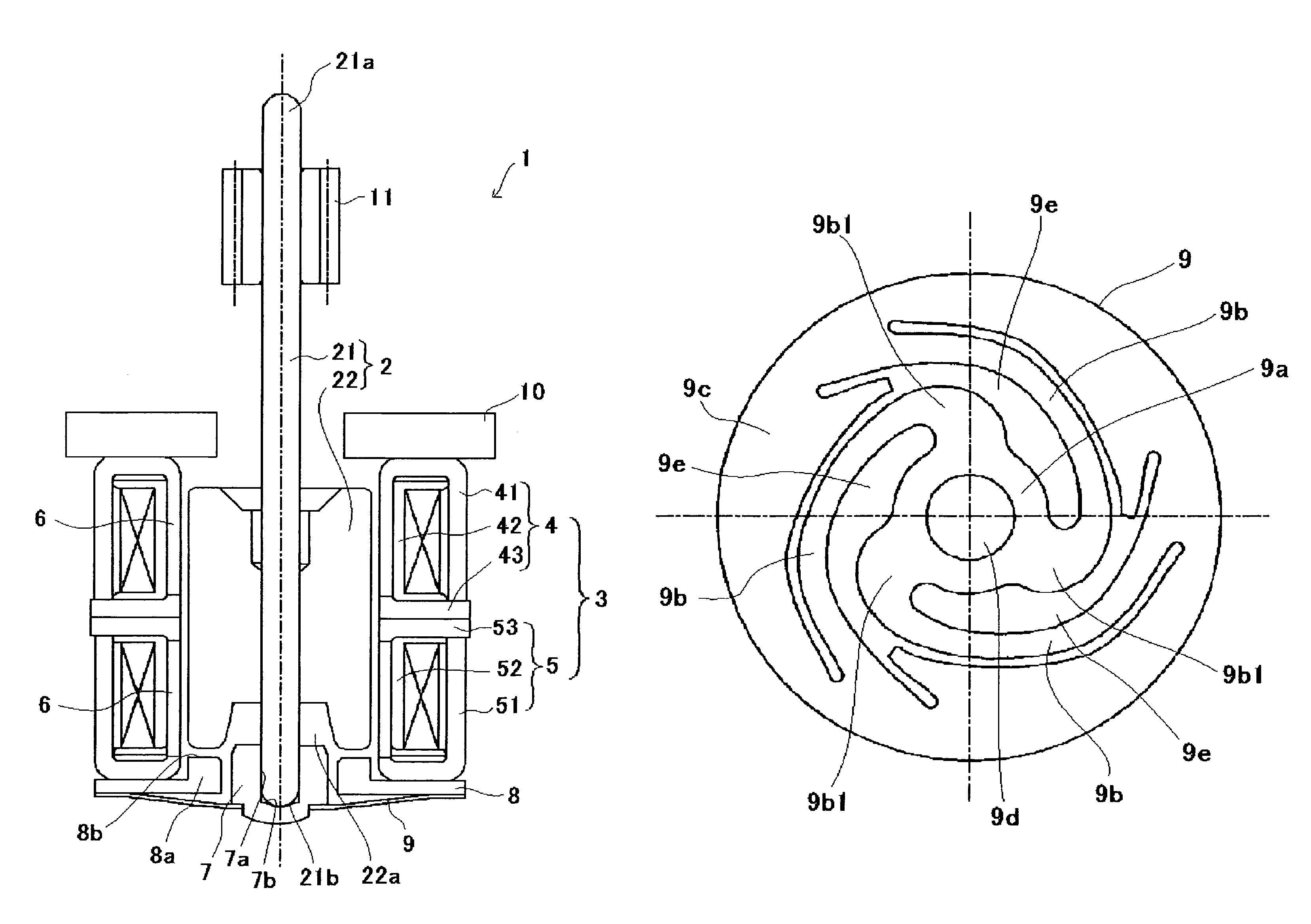
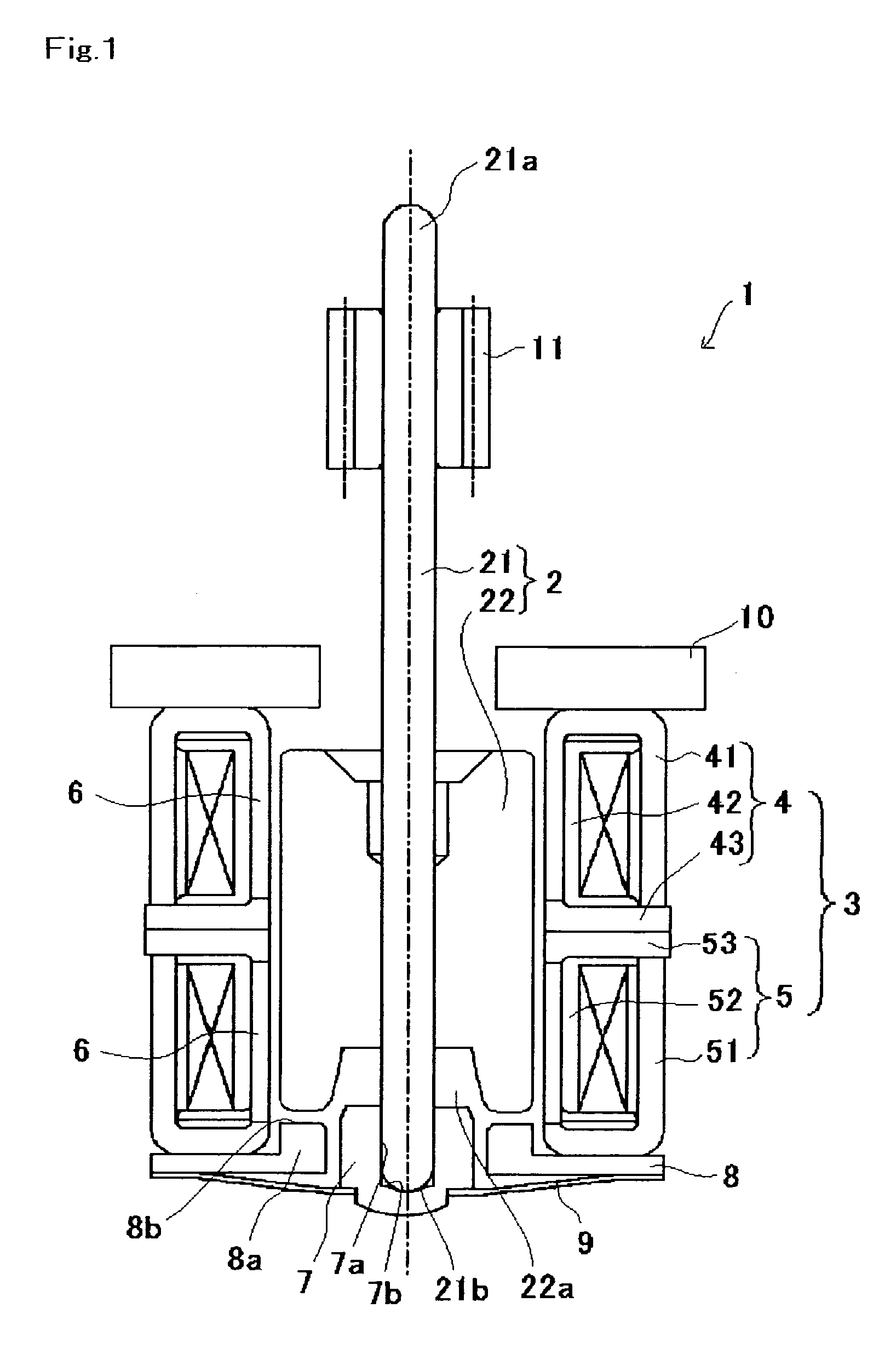
[0028]FIG. 1 is a cross-sectional side view showing a small motor in accordance with an embodiment of the present invention. FIG. 2 is a plan view showing the bearing holding member of the small motor shown in FIG. 1.

[0029]A small motor 1 in accordance with an embodiment of the present invention is a so-called PM type stepping motor, which includes a rotor 2 having a rotor shaft 21 and a cylindrical permanent magnet 22, a stator 3 having pole teeth 6 facing the permanent magnet 22 in the radial direction, and a base plate 10 which is fixed to the stator 3 on the output end side of the rotor shaft 21. A restriction member 8 for restricting the moving amount of the rotor 2 in the thrust direction and a bearing holding member 9 are provided on the opposite-to-output end side of the stator 3 (the base end 21b side of the rotor shaft 21).

[0030]Both the output end 21a...


PUM


Abstract

A small motor including a rotor, a stator, a bearing member which supports the rotor shaft in the radial and thrust direction and a bearing holding member which holds the bearing member. The bearing holding member is formed in a thin plate-shaped elastic member and includes a bearing holding part which holds the bearing member, arm parts which are extended outward from the bearing holding part in the radial direction in a spiral manner, and an outer peripheral part which is connected to the arm part at a position outward in the radial direction of the bearing holding part and which is fixed to the stator.

Description

CROSS-REFERENCE TO RELATED APPLICATIONS[0001]This application claims priority to Japanese Application No. 2004-228747 filed Aug. 5, 2004, which is incorporated herein by reference.BACKGROUND OF THE INVENTION[0002]a) Field of the Invention[0003]The present invention relates to a small motor in which a rotor, which is constructed such that a permanent magnet is fixed on the outer periphery of a rotor shaft, is rotated in the inside of a stator.[0004]b) Description of the Related Art[0005]A small motor is used in a drive actuator or the like for moving an object which is, for example, an optical head device used in a CD player or a DVD player. It is known that a stepping motor can be used as the small motor in which a rotor, which is constructed so that a permanent magnet is fixed to the outer periphery of a rotor shaft, is rotated in the inside of a stator having pole teeth facing the permanent magnet in a radial direction (see, for example, Japanese Patent Laid-Open No. 2003-333794)....

Claims


Application Information

Patent Timeline
Patent Type & Authority Patents(United States)
IPC IPC(8): H02K5/16
CPCH02K5/1672H02K37/14H02K7/06
Inventor AGEMATSU, IKUO
Owner SANKYO SEIKI MFG CO LTD
Learn More