
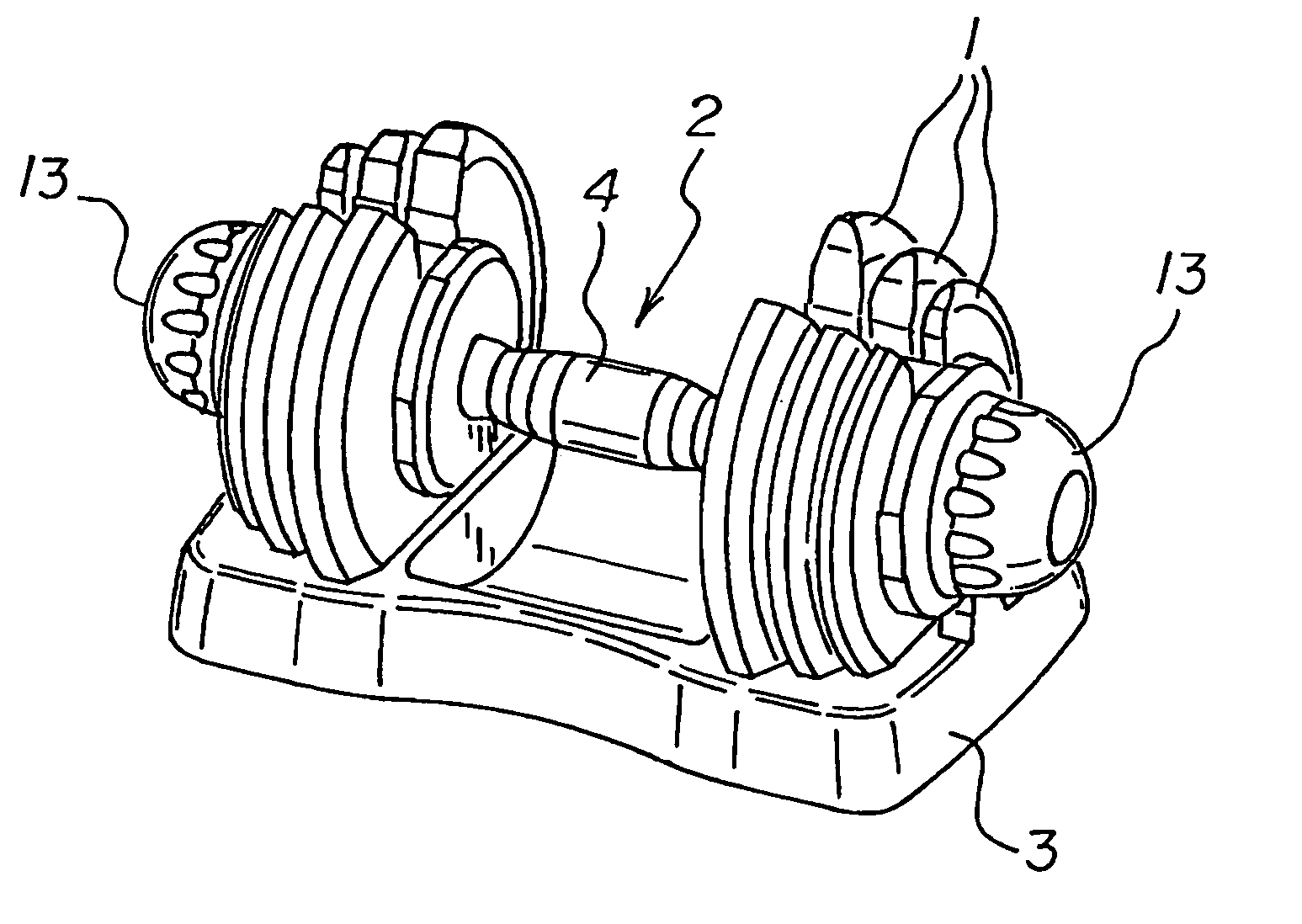
Adjustable dumbbell

a dumbbell and adjustable technology, applied in the field of adjustable dumbbells, can solve the problems of not describing an adjustable dumbbell that allows self-locking, high cost, and large volume of weight training instruments, and achieve the effects of low manufacturing cost, convenient and efficient manufacture and marketing, and durable and reliable construction

Inactive Publication Date: 2007-10-23
LIU PING
View PDF7 Cites 44 Cited by
  • Summary
  • Abstract
  • Description
  • Claims
  • Application Information

AI Technical Summary

Benefits of technology

The adjustable dumbbell provides a safe, reliable, and efficient way to change weights quickly, preventing slipping and allowing for continuous aerobic exercise, while being easy to assemble and store, thus overcoming the limitations of conventional dumbbells.

Problems solved by technology

While the prior art devices fulfill their respective, particular objectives and requirements, the prior patents do not describe an adjustable dumbbell that allows self-locking for use and adjusting for storage of exercise equipment.
There are many disadvantages of commonly-used weight-lifting instruments.
Weight training instruments, generally, are large in volume, expensive, and difficult to maintain, therefore, they are quite inconvenient to use.
For example, they are generally complex structures composed of cables, belt pulleys, weight and other mechanisms permitting various exercise on a single machine.
However, the connection of these clamping rings or clips is troublesome, and the connection is also unsafe, especially when becoming worn or broken when, as a result, they become difficult to place in a secure position.
Assembling particular weights on a simple weight-lifting instrument is tedious.
Each of the weights must be placed on an individual storing location which not only increases the time for assembling the weights, but also inevitably causes the weights to be scattered around the weight-lifting area.
Thus, individuals using the simple weight-lifting instrument are unable to exercise aerobically due to the requirements of withdrawing the weights and assembling and fixing them onto the shaft.
The individual cannot maintain a high heart rate while spending time in repeatedly withdrawing, assembling and fixing weights.
Accordingly, these dumbbells are not convenient for use and storage.
The result is the risk of weights slipping off during use.

Method used


Image

  • Adjustable dumbbell
  • Adjustable dumbbell
  • Adjustable dumbbell

Examples


Embodiment Construction

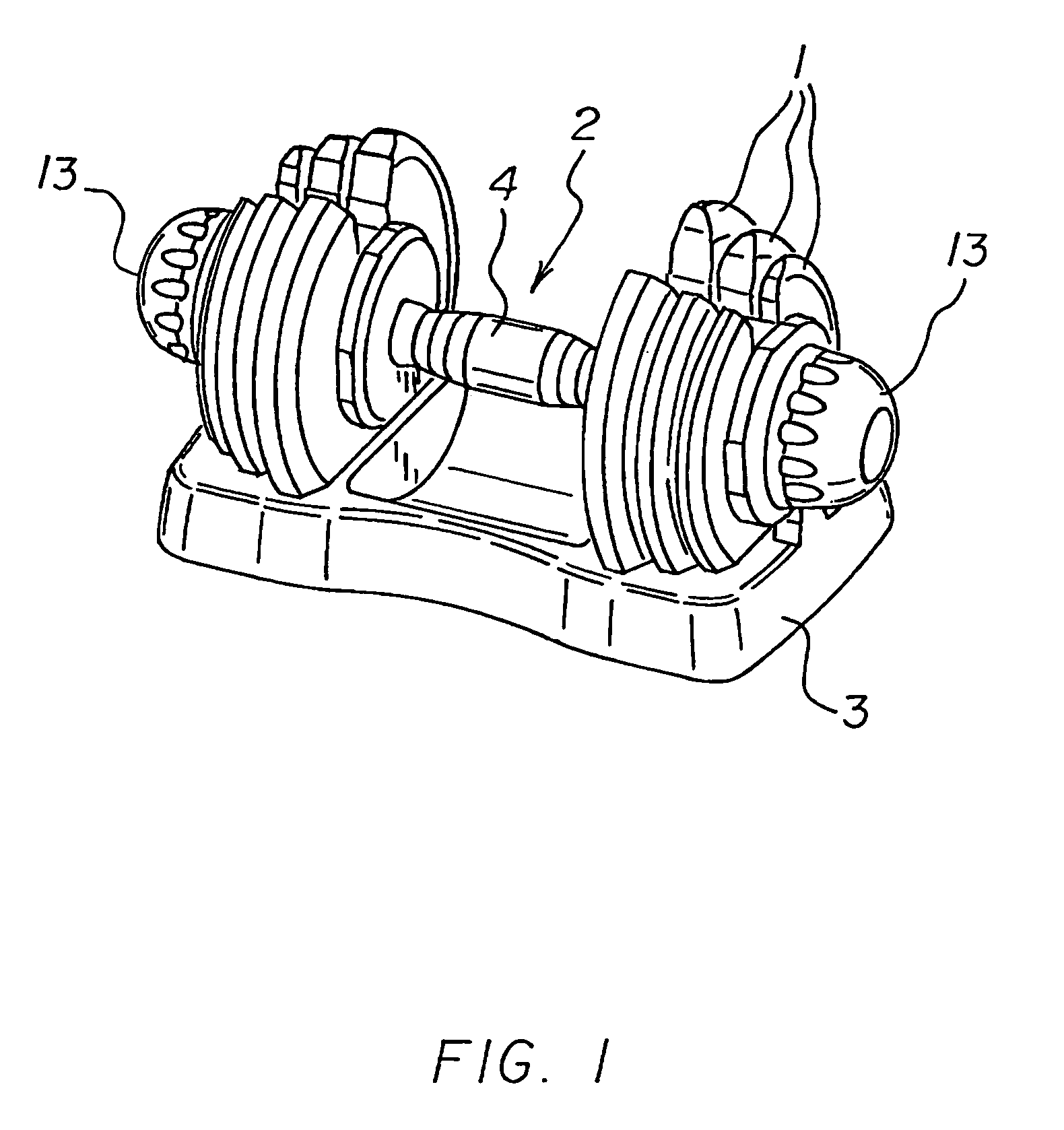
[0043]With reference now to the drawings, and in particular to FIG. 1 thereof, the preferred embodiment of the new and improved adjustable dumbbell embodying the principles and concepts of the present invention and generally designated by the reference numeral 10 will be described.

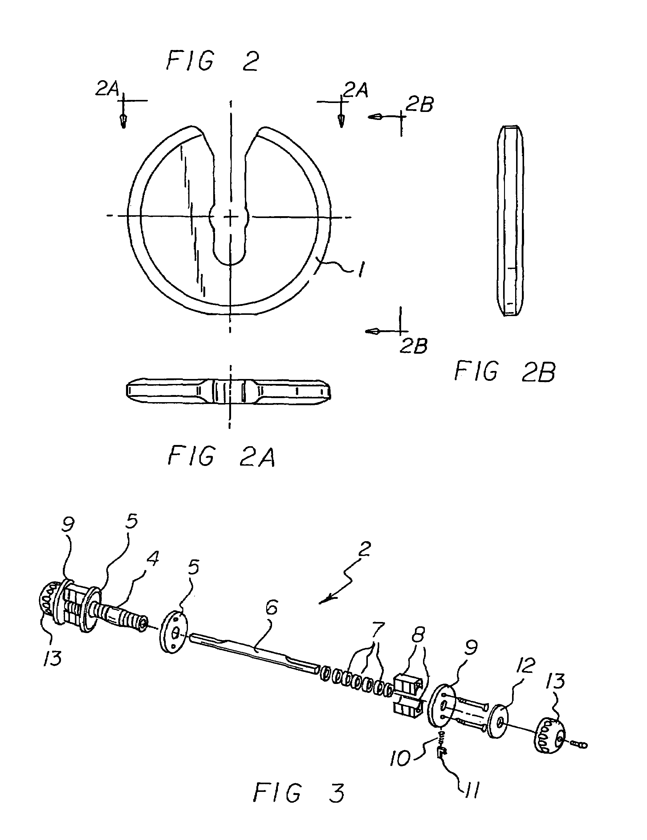
[0044]The present invention, the adjustable dumbbell 10 is comprised of a plurality of components. Such components in their broadest context include a plurality of weights including a set of weights, a shaft, and a holder. Such components are individually configured and correlated with respect to each other so as to attain the desired objective.

[0045]The adjustable dumbbell can be self-locked in use and adjusted for storage. Note FIG. 1. First provided is a plurality of weights 1. Note FIGS. 2, 5, 7 and 8. Each weight has a central hole and a slot extending through the central hole and extending to both sides from the central hole. Each slot has one end passing through the central hole to a point below the...


PUM


Abstract

Each of a plurality of weights has a central hole and a slot extending through the central hole. A shaft has a grip handle. A rotatable spindle extends through the grip handle with a plurality of cam plates adjacent to each end of the spindle and an adjustment knob at each end of the spindle. The cam plates each have an outer diameter adapted to fit the central hole of a weight. The weights include a set of weights positioned adjacent to each end of the rotatable spindle and adjacent to the cam plates. A holder is cooperable with the shaft with protrusion blocks adapted to cooperate with the shaft to form a self-locking mechanism.

Description

RELATED APPLICATIONS[0001]This application claims the benefit of foreign applications filed 24 Mar. 2006 in China, Number 200620025625.4 and EPO 29 May 2006 in the EPO, Number 06252637, the subject matter of which is incorporated herein by reference.BACKGROUND OF THE INVENTION[0002]1. Field of the Invention[0003]The present invention relates to exercise equipment, and particularly to an adjustable dumbbell which can be self-locked in use and adjusted for storage.[0004]2. Description of the Prior Art[0005]The use of dumbbells of known designs and configurations is known in the prior art. More specifically, dumbbells of known designs and configurations previously devised and utilized for the purpose of changing the weight for use are known to consist basically of familiar, expected, and obvious structural configurations, notwithstanding the myriad of designs encompassed by the crowded prior art which has been developed for the fulfillment of countless objectives and requirements.[0006...

Claims


Application Information

Patent Timeline
Patent Type & Authority Patents(United States)
IPC IPC(8): A63B21/072A63B21/075
CPCA63B21/0728A63B21/075A63B21/00065Y10S482/908A63B2021/0783A63B21/0783
Inventor LIU, PING
Owner LIU PING
Learn More