
Sound augmentation system and method for a drum

Inactive Publication Date: 2007-10-16
COOLIDGE CURTIS J
View PDF13 Cites 35 Cited by
  • Summary
  • Abstract
  • Description
  • Claims
  • Application Information

AI Technical Summary

Benefits of technology

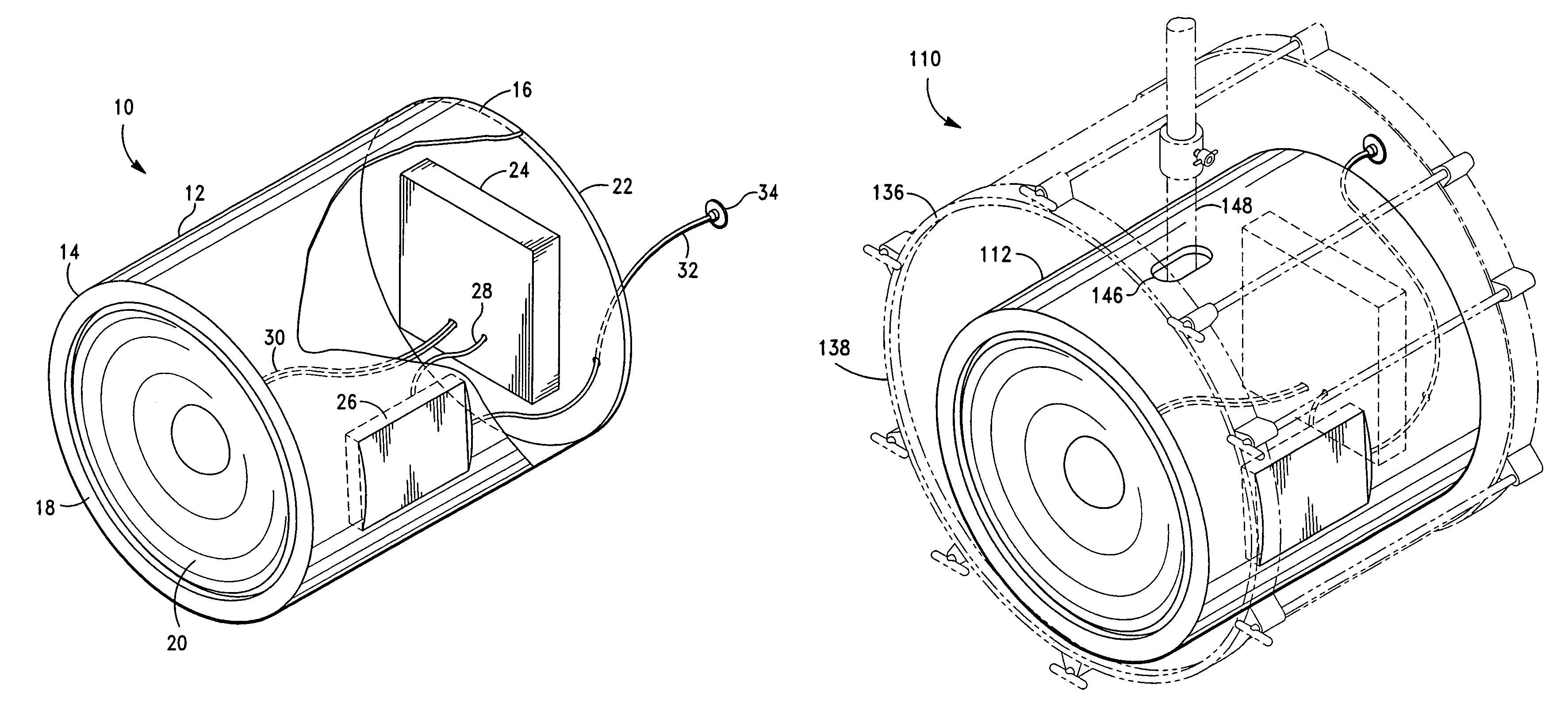
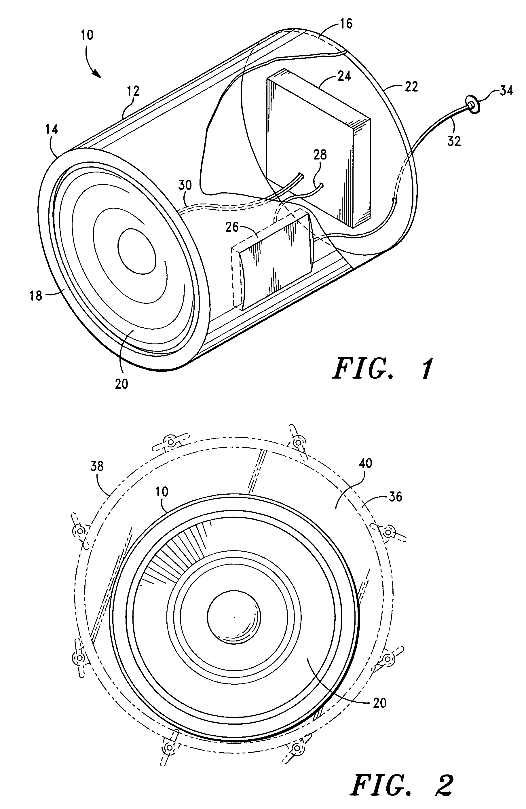
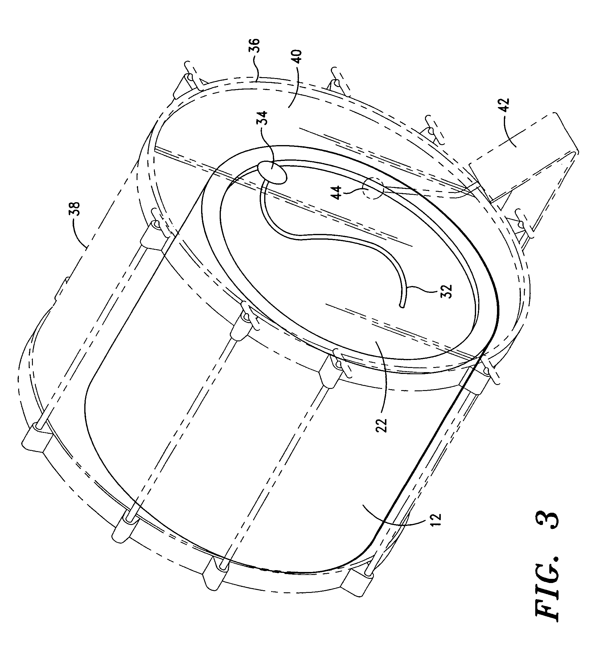
[0012]The present invention is directed to a sound augmentation system for a drum having a wave generator for generating an electrical signal corresponding to a predetermined sound, an amplifier for amplifying the electrical signal from the wave generator, and a driver for translating the amplified electrical signal to sound waves. The wave generator, amplifier, and driver are co-located in close proximity, or attached to a support structure, so that they may be placed together within a drum body. The system provides compact, inexpensive sound augmentation for drums while retaining the traditional feel of the drum for the drummer.
[0014]In a second exemplary embodiment, the sound augmentation system includes an elongated hole formed through an upper area of the support structure to provide mechanical stabilization of the system within a drum body. A support rod, such as the support rod from a double tom holder extending through the top of the kick drum body, is inserted into the elongated hole. With the rod inserted into the elongated hole, the system is prevented from rolling or turning within the drum body.

Problems solved by technology

Small clubs, however, present challenges in providing a proper mix of amplification of the various instruments.
Drums, however, present a unique challenge in a small club setting.
While the volume and relatively high frequency of the tom drums is typically sufficient to be discerned clearly without amplification, the lower frequency of the bass, or kick, drum can be easily lost beneath the multi-frequency, higher volume mix of the other instruments.
The loss of definition of the kick drum is particularly pronounced when an electric bass guitar is being used.
Various ways to alleviate this problem have been proposed and attempted, but each suffers from its own drawbacks.
In small venues, however, it is not always possible to place a microphone and an additional large amplifier and speaker where it does not interfere with or take space from the rest of the stage.
Furthermore, available amplifiers and speakers capable of properly reproducing the low frequency kick drum signal are intended for larger venues, and are thus more expensive and bulky, prohibiting their use in small venues.
However, electronic drum kits are unpopular since they entirely eliminate the acoustical and tactile elements of the drums they replace.
Electronic drum kits do not provide the feel that most drummers want or are accustomed to with their drums.

Method used


Image

  • Sound augmentation system and method for a drum
  • Sound augmentation system and method for a drum
  • Sound augmentation system and method for a drum

Examples


Embodiment Construction

[0023]Sound augmentation systems for a drum in accordance with various exemplary embodiments of the present invention are depicted in FIGS. 1 through 5. While the invention will be described in detail hereinbelow with reference to these exemplary embodiments, it should be understood that the invention is not limited to the specific configurations shown in these embodiments. Rather, one skilled in the art will appreciate that a variety of configurations may be implemented in accordance with the present invention.

[0024]Looking first to FIG. 1, a sound augmentation system for a drum in accordance with a first exemplary embodiment of the present invention is depicted generally by the designation 10. As can be seen, system 10 includes a tubular support structure or housing 12 that extends between an opening at first end 14 and an opening at second end 16. A circular rim 18 extends circumferentially around the opening at first end 14. A circular driver 20 (which will be described in great...


PUM


Abstract

A sound augmentation system for a drum comprises a wave generator for producing an electrical signal corresponding to a predetermined sound, an amplifier for amplifying the electrical signal to produce an amplified electrical signal, and a driver for translating the amplified electrical signal to a plurality of sound waves. The wave generator, amplifier and driver are mounted to a support structure configured to fit within a body of the drum. In operation, a strike of the head of the drum produces amplified sound waves that emanate from the body of the drum. Various embodiments of the sound augmentation system and associated method are provided.

Description

CROSS-REFERENCE TO RELATED APPLICATIONS[0001]This application claims priority to U.S. Provisional Application Ser. No. 60 / 554,967 filed on Mar. 18, 2004, which is hereby incorporated by reference herein in its entirety.STATEMENT REGARDING FEDERALLY SPONSORED RESEARCH OR DEVELOPMENT[0002]Not applicable.BACKGROUND OF THE INVENTION[0003]1. Field of the Invention[0004]The present invention relates to musical instrument sound producing devices, and more particularly to a sound augmentation system for use with a drum.[0005]2. Description of Related Art[0006]Electrical and electronic amplifiers are commonly used in the music industry to provide proper sound volume throughout the venue in which musicians, bands or other performers play. Large arenas typically require massive amplifiers and speakers to fill the venue with sound, while smaller clubs require correspondingly smaller amplifiers and speakers.[0007]Small clubs, however, present challenges in providing a proper mix of amplification...

Claims


Application Information

Patent Timeline
IPC IPC(8): G10H3/00
CPCG10H3/143G10H2250/435G10H2240/321
Inventor COOLIDGE, CURTIS J.
Owner COOLIDGE CURTIS J
Learn More