
Bolt driven connector

a connector and bolt technology, applied in the direction of connection, electrical apparatus, coupling device connection, etc., can solve the problems of insufficient insertion of first terminal fitting, inability to move the tpa member to the full locking position, etc., to prevent or limit the movement of the nu

Inactive Publication Date: 2007-10-16
SUMITOMO WIRING SYST LTD
View PDF9 Cites 4 Cited by
  • Summary
  • Abstract
  • Description
  • Claims
  • Application Information

AI Technical Summary

Benefits of technology

The invention is a bolt driven connector assembly that includes two housings that can be connected together. The assembly includes a terminal position assurance (TPA) member that can move between a partial locking position and a full locking position. The TPA member is designed to ensure that the first terminal fitting is properly inserted into the first housing. The connector assembly also includes a nut and a bolt that are rotatably mounted in the second housing. The nut is held non-rotatably in the first housing and is securely retained using a TPA member and / or the first housing. The bolt and nut are mounted centrally in the housings to balance forces during mating or unmating. The technical effects of this invention include improved reliability, secure and easy assembly, and balancing of forces during mating or unmating.

Problems solved by technology

However, the TPA member cannot be moved to the full locking position if the first terminal fitting is mounted only partly into the first housing.
Thus, an inability to move the TPA member to the full locking position provides an indication that the first terminal fitting has not been inserted sufficiently.

Method used


Image

  • Bolt driven connector
  • Bolt driven connector
  • Bolt driven connector

Examples


first embodiment

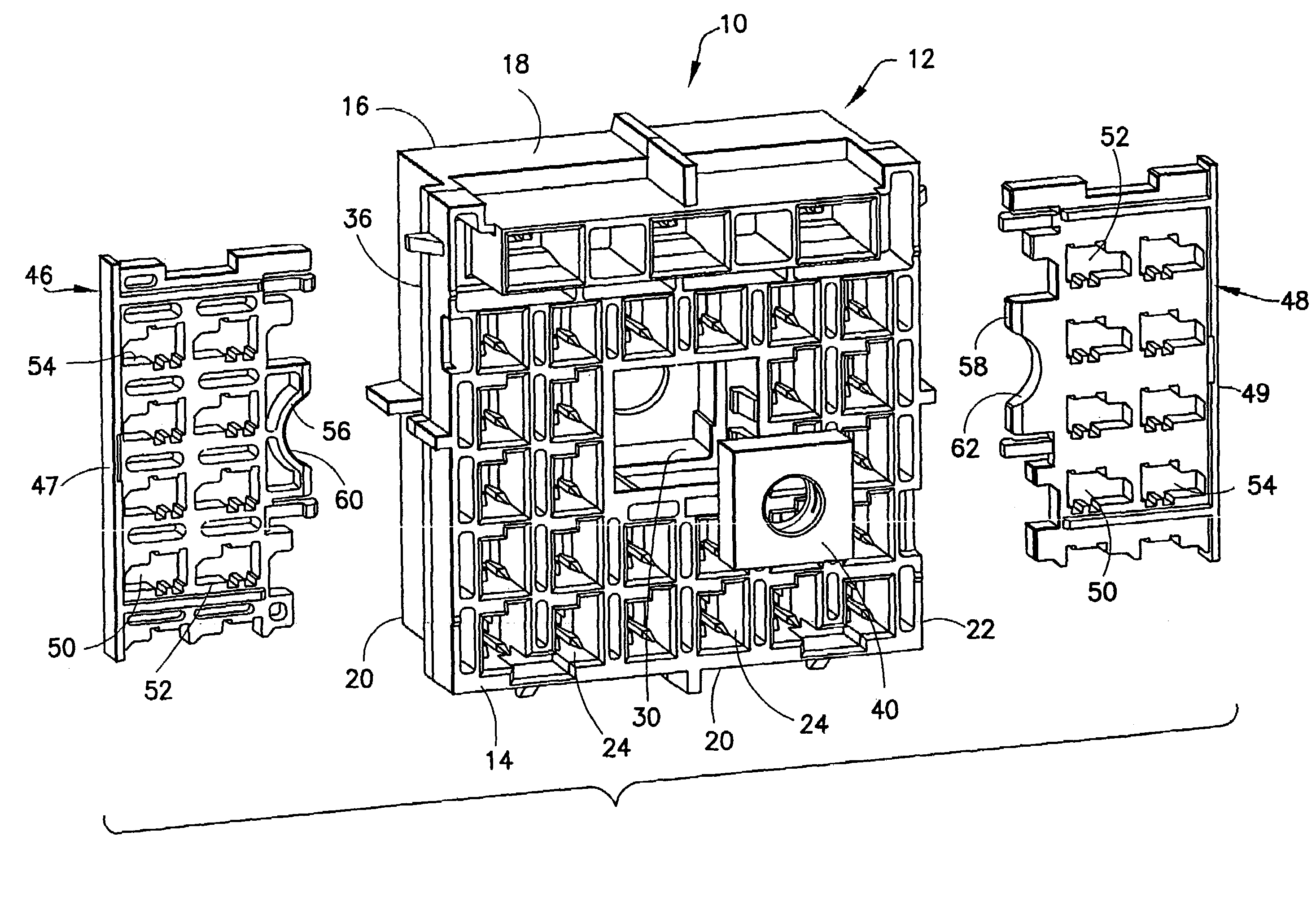
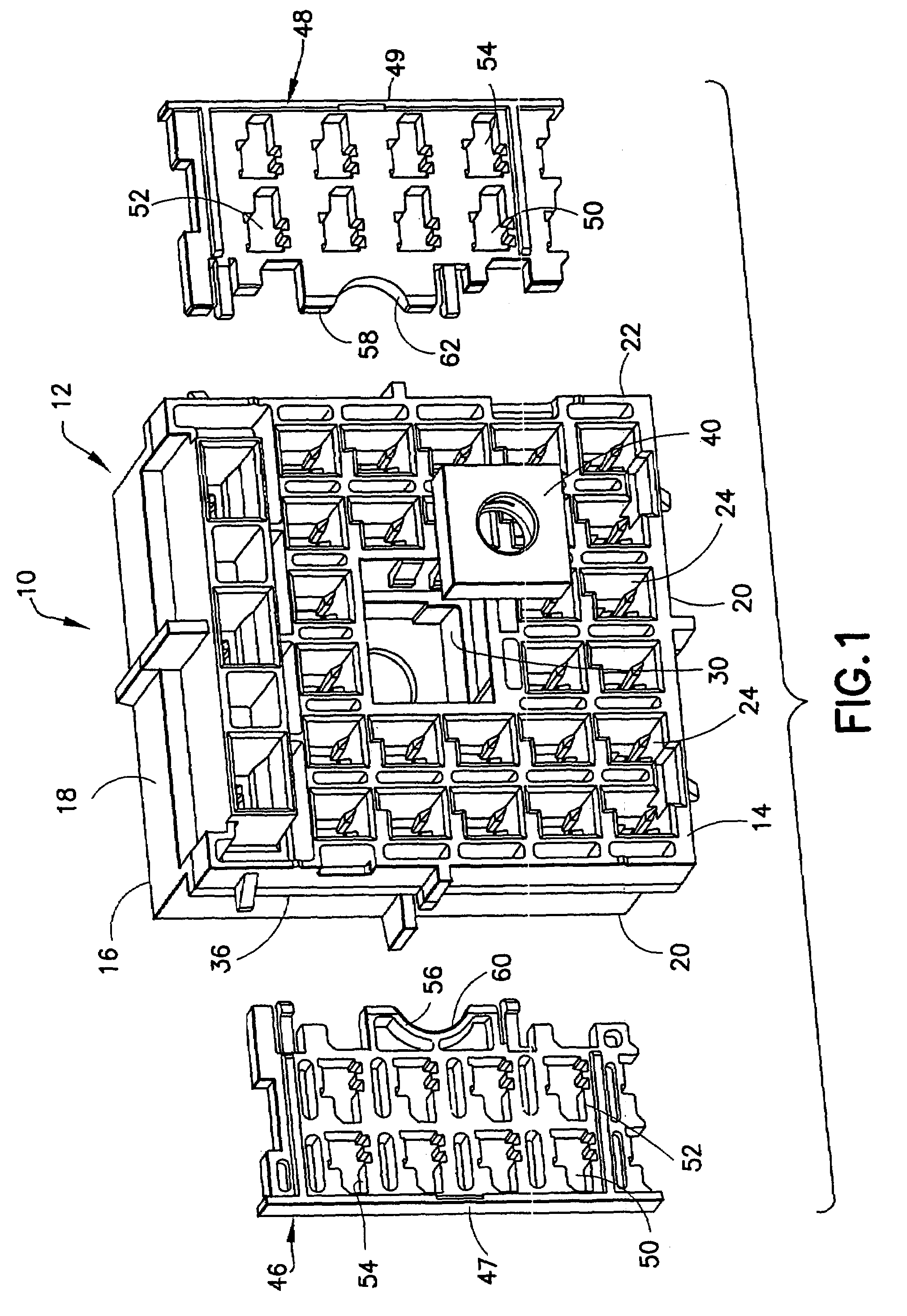
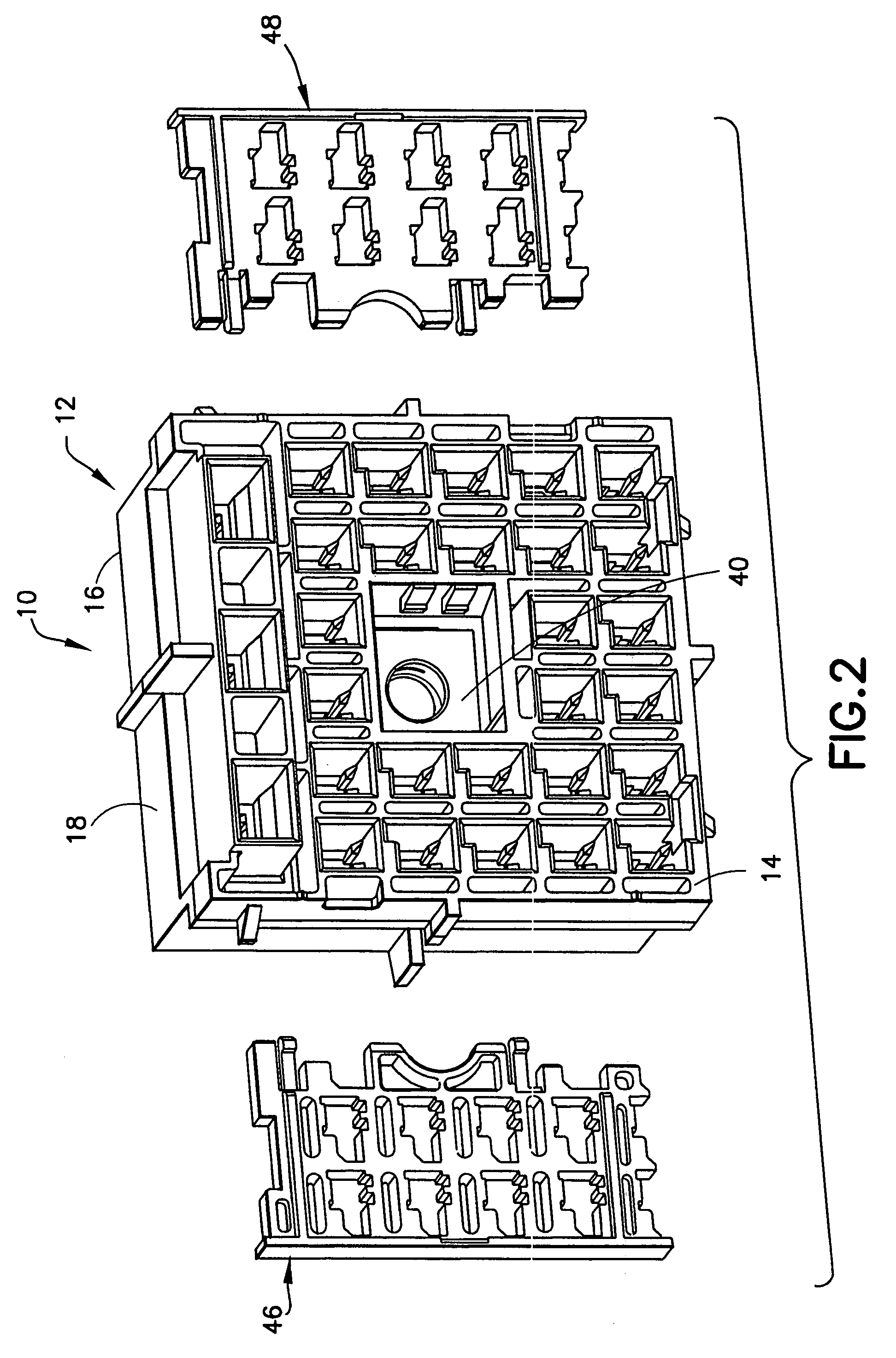
[0027]A bolt driven connector assembly in accordance with the invention is identified by the numeral 10 in FIGS. 1-5. The connector assembly 10 includes a housing 12 that is molded unitarily from a non-conductive synthetic resin. The housing 12 has a substantially rectilinear block shape with opposite rear and front ends 14 and 16 respectively. The rear end 14 of the housing 12 is configured for connection with a mating housing (not shown). Opposite top and bottom walls 18 and 20 extend from the rear end 14 to the front end 16 of the housing 12. The terms top and bottom are used herein as a convenient frame of reference, and do not imply a required gravitational frame of reference for the connector 10. Opposite first and second side walls 20 and 22 also extend between the rear and front ends 14 and 16 of the housing 12 and connect the top and bottom walls 18 and 20.

[0028]Cavities 24 extend through the housing 12 along direction A from the rear end 16 substantially to the rear end 14...

second embodiment

[0039]FIGS. 6-10 show a connector assembly 70 in accordance with the invention. The connector assembly 70 includes a housing 72 that is molded unitarily from a non-conductive synthetic resin. The housing 72 has a substantially rectilinear block shape with opposite front and rear ends 74 and 76 respectively. The front end 74 of the housing 72 is configured for connection with a mating housing (not shown). Opposite top and bottom walls 78 and 80 extend from the front end 74 to the rear end 76 of the housing 72. The terms top and bottom are used herein as a convenient frame of reference, and do not imply a required gravitational frame of reference for the connector 70. Opposite first and second side walls 82 and 84 also extend between the front and rear ends 74 and 76 of the housing 82 and connect the top and bottom walls 78 and 80.

[0040]Cavities 85 extend through the housing 72 along direction “A” from the rear end 76 substantially to the front end 74. The cavities 85 are configured t...


PUM


Abstract

A bolt-driven connector (10; 70) includes a housing (12; 72) with cavities (24; 84) extending in front to rear directions through the housing (12; 72). At least one position assurance slot (36, 38; 90) extends into the housing (12; 72) in a direction transverse to the cavities (24; 84) and slidably receives at least one TPA member (46, 48; 92) for assuring the position of the terminal fittings in the cavities (24; 84). A threaded insert (40) is held connector (10; 70) and is prevented from rotating relative to the housing (12; 72) by walls (30) the housing (12) or walls (98) of the TPA member (92). Forward movement of the threaded insert (40) is prevented by a wall (32; 87) of the housing (12; 72) and rearward movement is prevented by either a wall (87) of the housing (72) or a wall (56, 58) of the TPA member (46, 48).

Description

BACKGROUND OF THE INVENTION[0001]1. Field of the Invention[0002]The invention relates to a connector with two housings and a bolt that generates forces to connect or disconnect the housings.[0003]2. Description of the Related Art[0004]Prior art connectors include first and second housings that can be connected to one another. Terminal fittings are mounted in each housing. The terminal fittings in the first housing are disposed to mate with the terminal fittings in the second housing when the housings are connected properly.[0005]Connectors that are used in automotive vehicles often affect critical aspects of the vehicle operation. Performance of these important vehicular functions depends partly upon proper positioning of the terminal fittings in the housings. Proper positioning of the terminal fittings is complicated by the frequent vibration of the automotive vehicle and the broad range of temperature to which the vehicle may be exposed during normal use. Most connectors include l...

Claims


Application Information

Patent Timeline
Patent Type & Authority Patents(United States)
IPC IPC(8): H01R13/627
CPCH01R13/6215H01R13/4361
Inventor STOCK, CHRISTOPHER W.
Owner SUMITOMO WIRING SYST LTD
Learn More