
Support grid apparatus and method

a technology of support grid and support rod, which is applied in the direction of carburetor air, lighting and heating apparatus, and separation processes, etc., can solve the problems of splash bars being dislodged or loose, the aforementioned support grid and bar attachment features have drawbacks, and the use of support grids which employ separate wires or clips can be somewhat costly

Inactive Publication Date: 2007-10-02
SPX COOLING TECH
View PDF12 Cites 7 Cited by
  • Summary
  • Abstract
  • Description
  • Claims
  • Application Information

AI Technical Summary

Benefits of technology

The present invention provides a support grid and method for installing and retaining a splash bar on a cooling tower. The support grid includes a frame with columns and girts that intersect to form windows with a width and height. The frame has first and second retainers that extend from the frame into the windows to support the splash bar. The method involves sliding the splash bar on slider portions and transitioning it to engage the first retainer before retaining it via the second retainer. The technical effects of the invention include improved cooling efficiency, reduced noise, and improved stability of the cooling tower.

Problems solved by technology

The support grids typically employ bar attachment features such as separate wires or clips that secure the individual splash bars to the support grids, because there is a tendency for the splash bars to become dislodged or loose, due to impingement by water and the air flow through the cooling tower.
The aforementioned support grids and bar attachment features have drawbacks however.
The use of the support grids which employ the separate wires or clips can be somewhat costly in terms of material cost and / or the amount of time required for installation, because present techniques for mounting the wire or clips are undesirable and labor intensive.
Also, while the support grids with integral clips alleviate some or all of the labor required to mount the individual clips, the presence of the internal clips can make the mounting of splash bars difficult during cooling tower assembly.
The aforementioned sliding of the bars oftentimes causes the splash bars to snag or catch the integral clips, causing the clips to deform or break.
Thus, installation of the of the splash bars again becomes labor intensive, requiring that the bars be supported or lifted over the clips by multiple “installers” in order to prevent the deformation or breaking of the clips during splash bar installation.

Method used


Image

  • Support grid apparatus and method
  • Support grid apparatus and method
  • Support grid apparatus and method

Examples


Embodiment Construction

[0024]Various preferred embodiments of the present invention provide for a support grid with unitary clips and sliders for supporting splash bars in cooling tower assemblies, for example. In some arrangements, the support grid having unitary clips and sliders may also be employed in heating towers, for example. It should be understood, however, that the present invention is not limited in its application to cooling towers or heating towers, but, for example, may be used with other tower like structures requiring supporting structures or the like. Preferred embodiments of the invention will now be further described wither reference to the drawing figures, in which like reference numerals refer to like parts throughout.

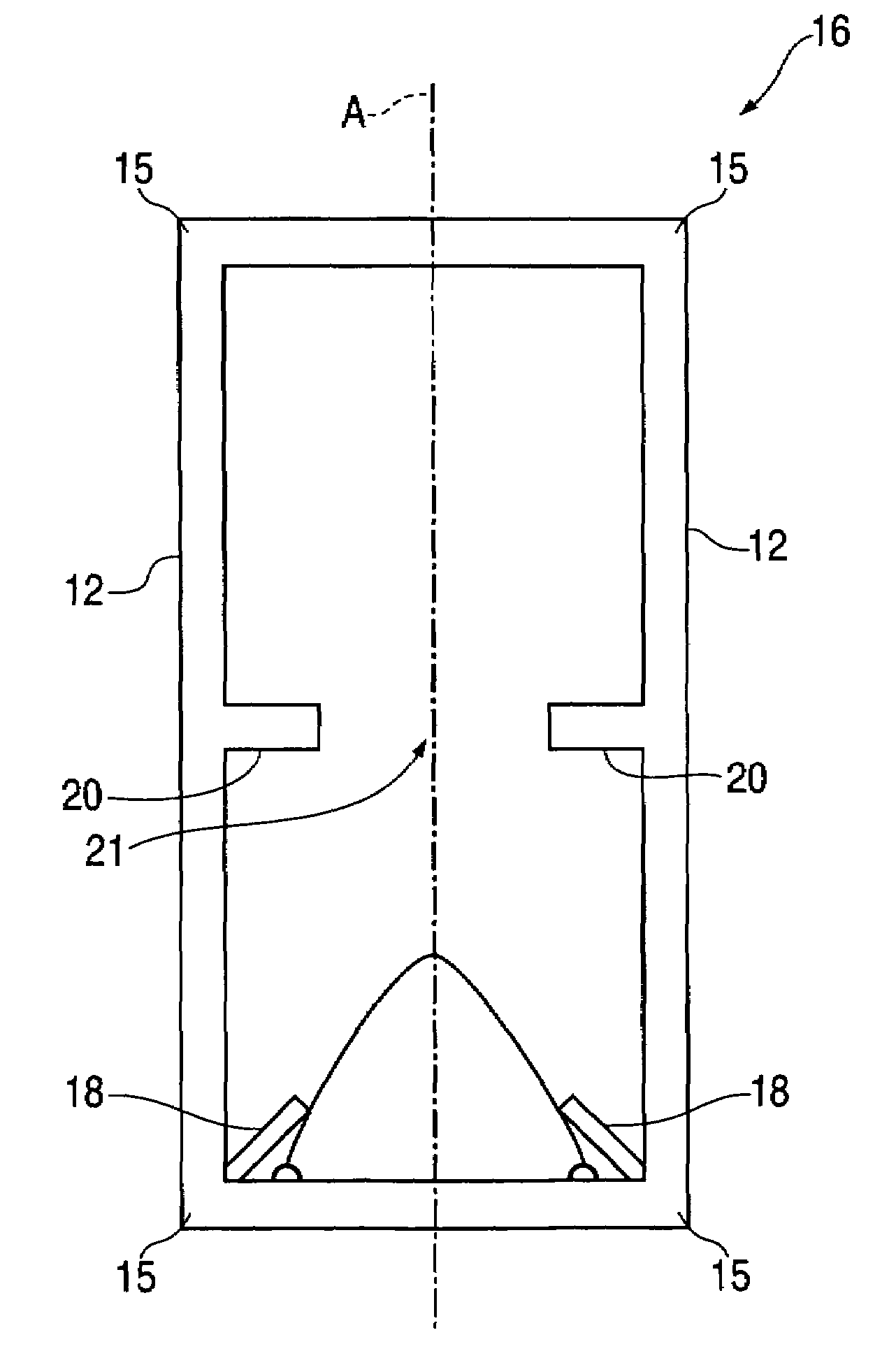
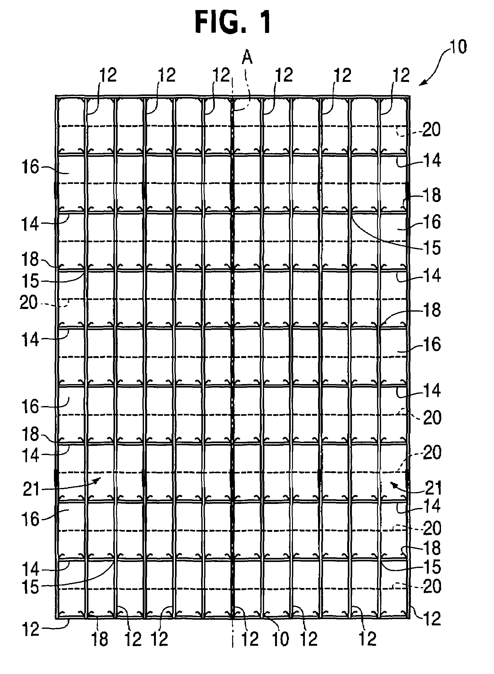
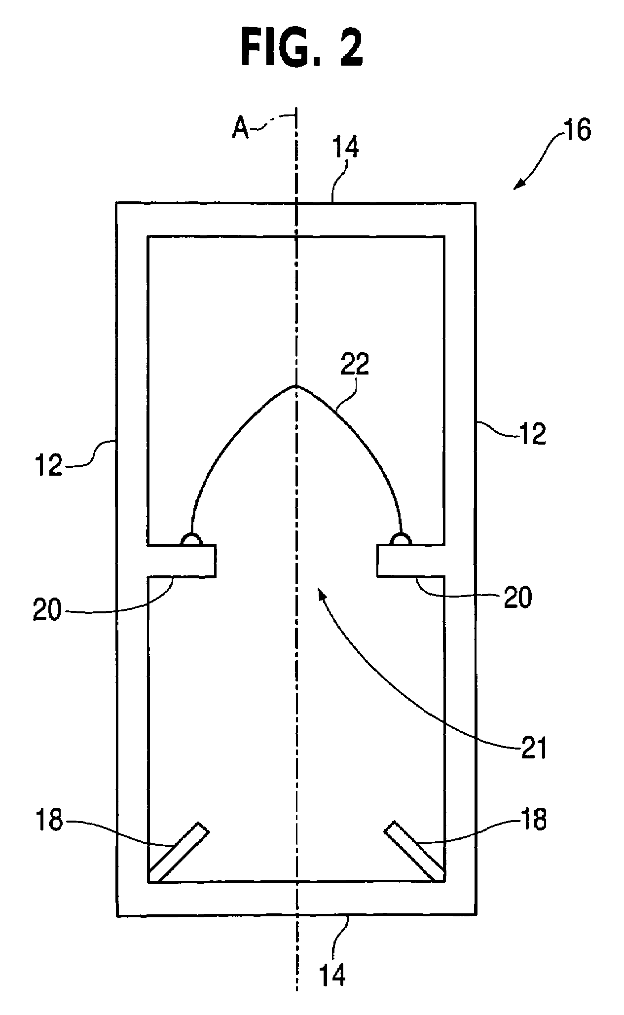
[0025]Referring now to FIG. 1, a support grid, generally designated 10, for supporting splash bars in a cooling tower is illustrated. The support grid 10 includes a plurality of vertical column portions 12 and horizontal girt portions 14. The vertical columns 12 and hor...


PUM

PropertyMeasurementUnit
heightaaaaaaaaaa
heightaaaaaaaaaa
heightaaaaaaaaaa

Abstract

A support grid having a longitudinal axis, having a frame. The frame includes a series of columns that extend generally parallel to the longitudinal axis and a series of girts that intersect the series of columns to form a plurality of windows. The support grid also includes a first retainer integral with the frame. The first retainer extends from the frame into at least one of the plurality of windows at a first axial location. The support grid also includes slider portions that extend in opposed relation for the frame into the at least one plurality of windows.

Description

FIELD OF THE INVENTION[0001]This invention relates generally to an apparatus and method for supporting splash bars or the like in a cooling tower, for example. More particularly, the present invention relates, for example, to an improved apparatus and method for installing and supporting splash bars on a cooling tower support grid having unitary retaining clips.BACKGROUND OF THE INVENTION[0002]A number of heat exchange apparatuses exist wherein a liquid and a gas are brought into direct contact with each other for effecting a transfer of heat and mass from one fluid to the other, for example, cooling towers.[0003]In typical cooling tower constructions, hot liquid to be cooled gravitates downwardly through the cooling tower while air is simultaneously circulated through the tower. The cooling of the liquid is basically accomplished by the direct contact of the air and liquid, wherein heat is transferred from the surface of the liquid to the circulating air. The efficiency with which ...

Claims


Application Information

Patent Timeline
Patent Type & Authority Patents(United States)
IPC IPC(8): B01F3/04
CPCF28F25/082Y10S261/11
Inventor MOCKRY, ELDON F.KINNEY, JR., OHLER L.PULLEN, KATHRYN L.
Owner SPX COOLING TECH
Learn More