
Low jitter frequency synthesizer

a low-jitter frequency, synthesizer technology, applied in the direction of pulse automatic control, electrical equipment, etc., can solve the problems of power dissipation, phase jitter performance, increased die size,

Active Publication Date: 2007-09-25
INTEGRATED DEVICE TECH INC
View PDF11 Cites 41 Cited by
  • Summary
  • Abstract
  • Description
  • Claims
  • Application Information

AI Technical Summary

Benefits of technology

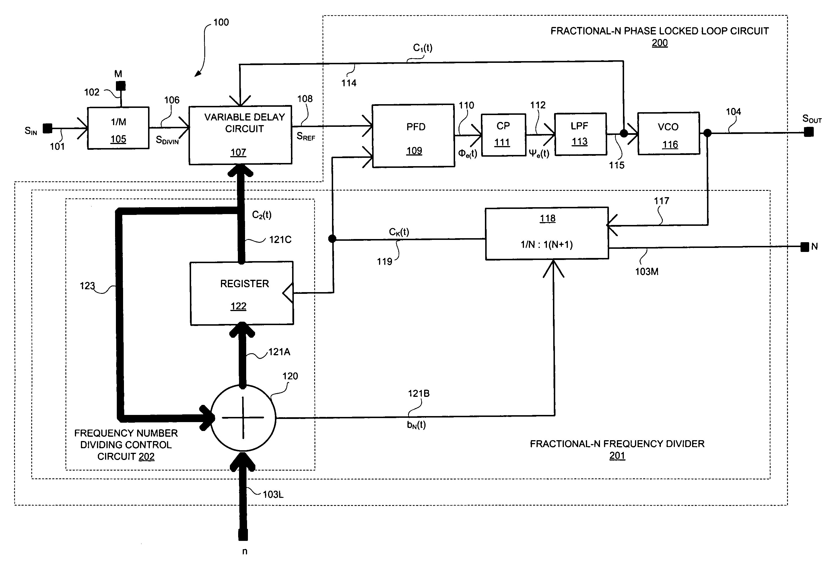
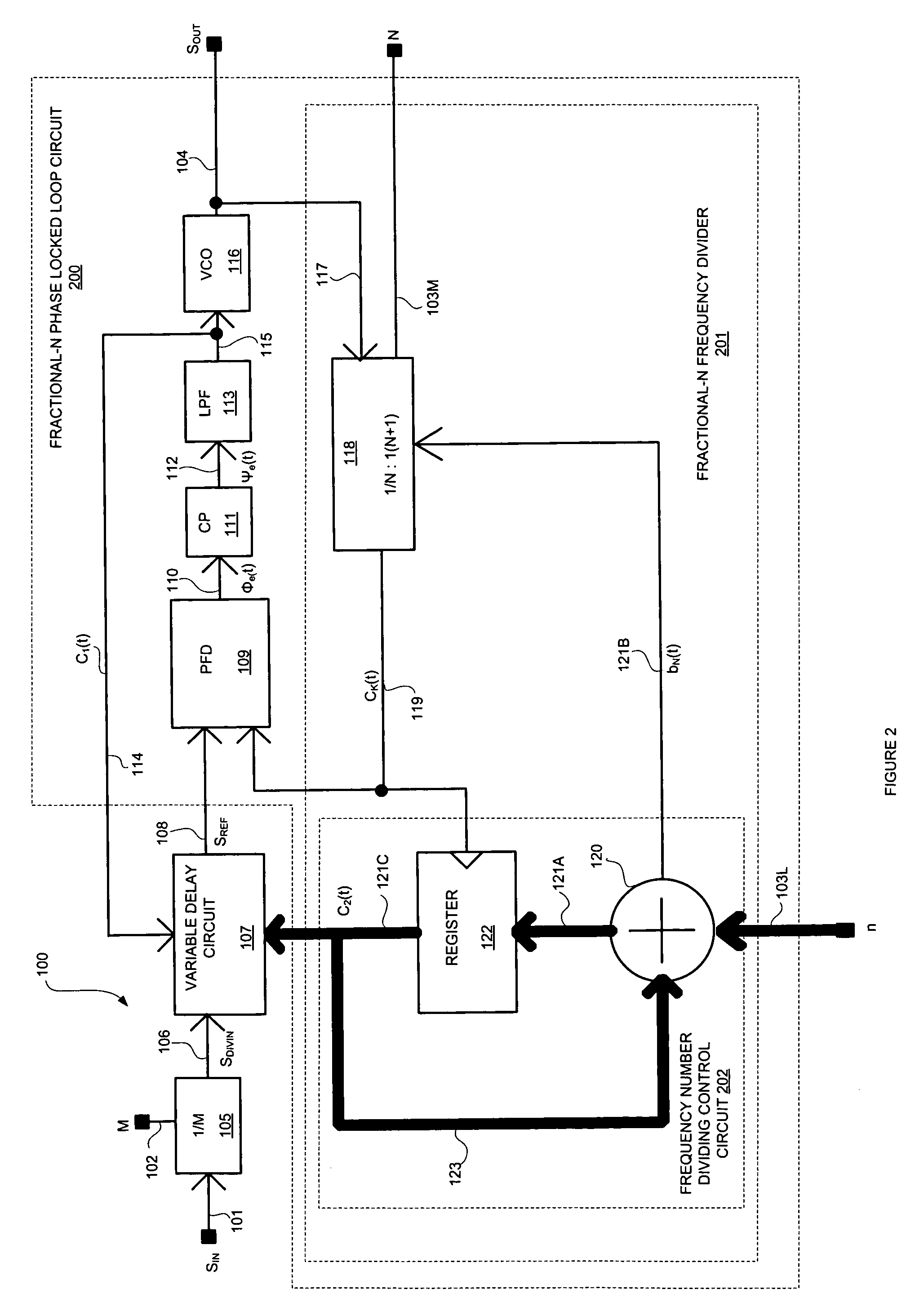
The present invention is a frequency synthesizer that solves problems with previous phase locked loop circuits. It includes a variable delay circuit and a feedback loop that anticipates and removes phase errors, resulting in a more stable output. This improves the overall performance of the frequency synthesizer.

Problems solved by technology

The technical problem addressed in this patent is the need for a high-speed PLL-based frequency synthesizer that produces an output frequency that is a fractional multiplication of the input frequency with good jitter noise performance, as well as a low jitter frequency synthesizer with good jitter noise performance. Existing methods have limitations such as tradeoffs between the ratio of N and M and power dissipation, or the use of sigma delta modulators that create spurious components and phase errors. The present invention aims to overcome these limitations and provide a more efficient and effective solution.

Method used


Image

  • Low jitter frequency synthesizer
  • Low jitter frequency synthesizer
  • Low jitter frequency synthesizer

Examples


Embodiment Construction

[0017]Reference will now be made in detail to the preferred embodiments of the invention, examples of which are illustrated in the accompanying drawings. While the invention will be described in conjunction with the preferred embodiments, it will be understood that they are not intended to limit the invention to these embodiments. On the contrary, the invention is intended to cover alternatives, modifications and equivalents, which may be included within the spirit and scope of the invention as defined by the appended claims. Furthermore, in the following detailed description of the present invention, numerous specific details are set forth in order to provide a thorough understanding of the present invention. However, it will be obvious to one of ordinary skill in the art that the present invention may be practiced without these specific details. In other instances, well-known methods, procedures, components, and circuits have not been described in detail so as not to unnecessarily...


PUM


Abstract

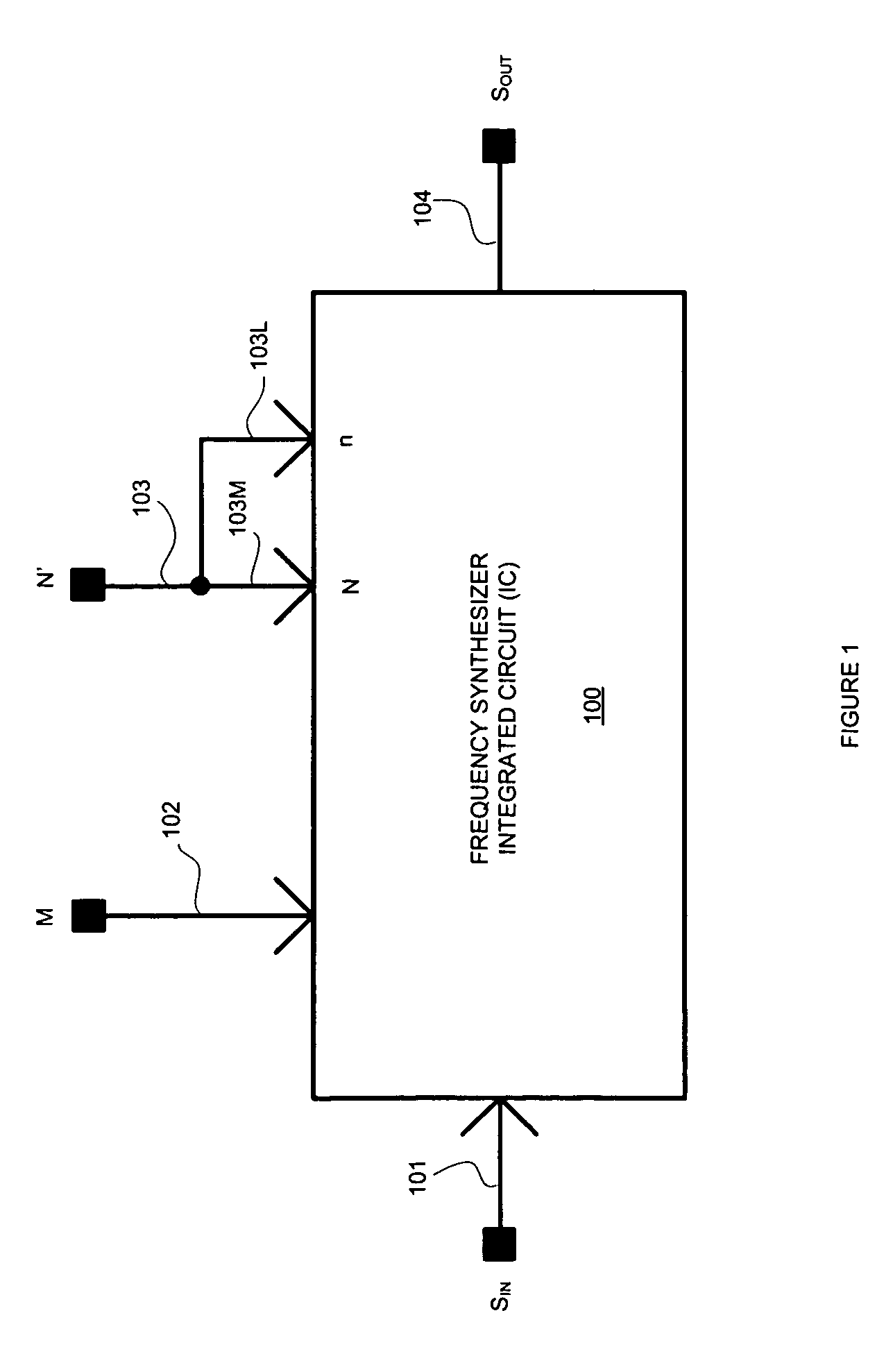
A frequency synthesizer IC is disclosed that includes a variable delay circuit, a fractional-N phase locked loop circuit, and a feedback loop. The variable delay circuit is electrically coupled to the input of the fractional-N phase locked loop circuit. The feedback loop couples a first control signal from the fractional-N phase locked loop to the variable delay circuit. The variable delay circuit generates a reference signal that has a phase delay that varies in accordance with a second control signal and a first control signal. The fractional-N phase locked loop circuit is operable upon receiving the reference signal to generate the first control signal, the second control signal, and an output signal having a frequency that is a non-integer product of the reference signal.

Description


Claims


Application Information

Patent Timeline
Owner INTEGRATED DEVICE TECH INC
Learn More