System and method for locating targets using measurements from a space based radar

a space-based radar and target technology, applied in the direction of instruments, measurement devices, using reradiation, etc., can solve the problem of based devices constantly moving

Active Publication Date: 2007-09-11
MITRE SPORTS INT LTD
View PDF8 Cites 6 Cited by
  • Summary
  • Abstract
  • Description
  • Claims
  • Application Information

AI Technical Summary

Problems solved by technology

Theses spaced-based devices may constantly move, and are typically not perfectly parallel with either the target and / or the ground plane of the planet.

Method used


Image

  • System and method for locating targets using measurements from a space based radar
  • System and method for locating targets using measurements from a space based radar
  • System and method for locating targets using measurements from a space based radar

Examples


Embodiment Construction

Overview

[0025]While specific configurations and arrangements are discussed, it should be understood that this is done for illustrative purposes only. A person skilled in the pertinent art will recognize that other configurations and arrangements can be used without departing from the spirit and scope of the present invention. It will be apparent to a person skilled in the pertinent art that this invention can also be employed in a variety of other applications.

Overall System

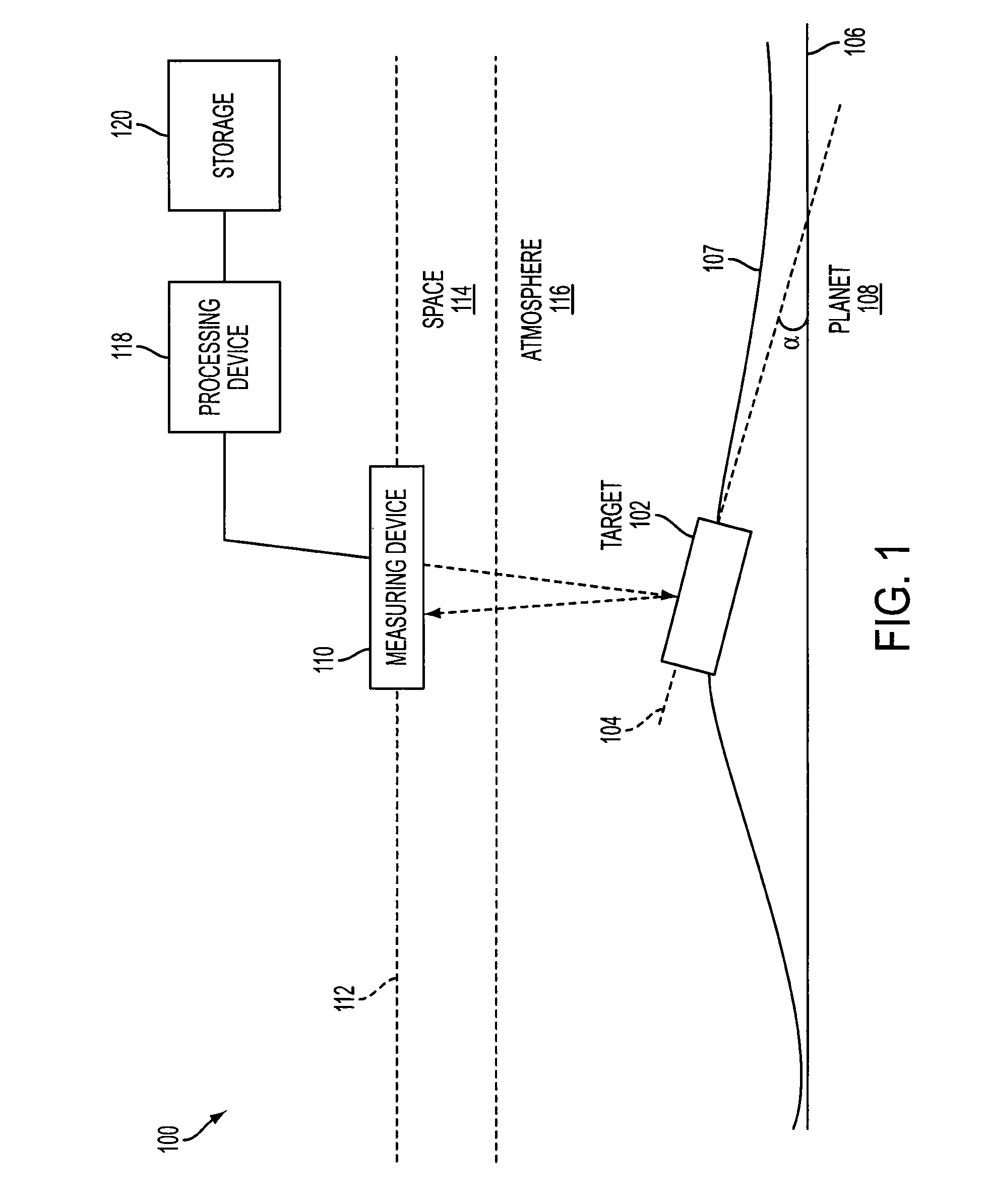
[0026]FIG. 1 shows a system 100, according to an embodiment of the present invention. System 100 includes a target 102 having a longitudinal axis 104 that is angled at an angle α with respect to a ground plane 106 of a planet 108. Target 102 is positioned on a surface 107 of planet 108. For example, a ground plane can be based on a plane tangential to a point on surface 107 that is of interest. System 100 also includes an airborne measuring device 110 having a airborne measuring device longitudinal axis 112. In o...


PUM


Abstract

A system and method for determining a position of a target within an acceptable tolerance using an iterative approach. A airborne or space-based measuring device is used to measure an estimated position of the target. The information from the measuring device is used in conjunction with either live captured or stored topography, or the like, information relating to the surface of the planet proximate the target to iteratively determine the actual position of the target.

Description

STATEMENT REGARDING FEDERALLY SPONSORED RESEARCH AND DEVELOPMENT[0001]Statement under MPEP 310. The U.S. government has a paid-up license in this invention and the right in limited circumstances to require the patent owner to license others on reasonable terms as provided for by the terms of Contract No. FA8721-04-C-0001, awarded by DARPA.BACKGROUND[0002]1. Field of the Invention[0003]The present invention relates to determining positions of targets using airborne measuring systems.[0004]2. Background Art[0005]Currently, measuring systems for measuring target positions from airborne measuring devices require the measuring device and target to be in planes parallel to each other and parallel to a ground plane of the target planet. If these two criteria are not met, the measurement accuracy is substantially reduced. Recently, there has been a need to measure targets that are on in planes that are not parallel to a ground plane of the planet (e.g., vehicles moving through mountains). A...

Claims


Application Information

Patent Timeline
Patent Type & Authority Patents(United States)
IPC IPC(8): G01S13/42
CPCG01S13/86G01S13/882
Inventor SANYAL, PROBAL K.
Owner MITRE SPORTS INT LTD
Why Eureka
Try Eureka