
Safety support for vehicle wheel

a safety support and vehicle wheel technology, applied in the direction of tire beads, vehicle components, without separate inflatable inserts, etc., can solve the problems of long implementation time, complicated installation and removal of wheel rims relative to wheel rims, etc., and achieve the effect of preventing the tubular structure ring from deflating and rapid pressure drop of tires

Inactive Publication Date: 2007-09-04
MICHELIN & CO CIE GEN DES ESTAB MICHELIN
View PDF10 Cites 7 Cited by
  • Summary
  • Abstract
  • Description
  • Claims
  • Application Information

AI Technical Summary

Benefits of technology

[0018]The vehicle wheel may also comprise, in particular in the case of a wheel whose rim has a width (the dimension measured parallel to the axis of rotation of the wheel) markedly greater than the width of the ring of the safety support, in particular in the case of a heavy truck wheel, at least one tire bead locking element which is placed around the rim between a lateral face of the ring of the safety support and a bead of the tire. In this case, the bead locking element may have the shape of a semi-rigid tubular structure ring, which is furnished with a valve used to inflate the tubular structure ring in the presence of a compressed gas in the tire of the wheel, and preventing the tubular structure ring from deflating when there is a rapid pressure drop in the tire.

Problems solved by technology

On the other hand, the safety supports of the segmented ring type have the disadvantage that their mounting on a wheel rim and their removal relative to the wheel rim are relatively complicated and take a long time to implement.

Method used


Image

  • Safety support for vehicle wheel
  • Safety support for vehicle wheel
  • Safety support for vehicle wheel

Examples


Embodiment Construction

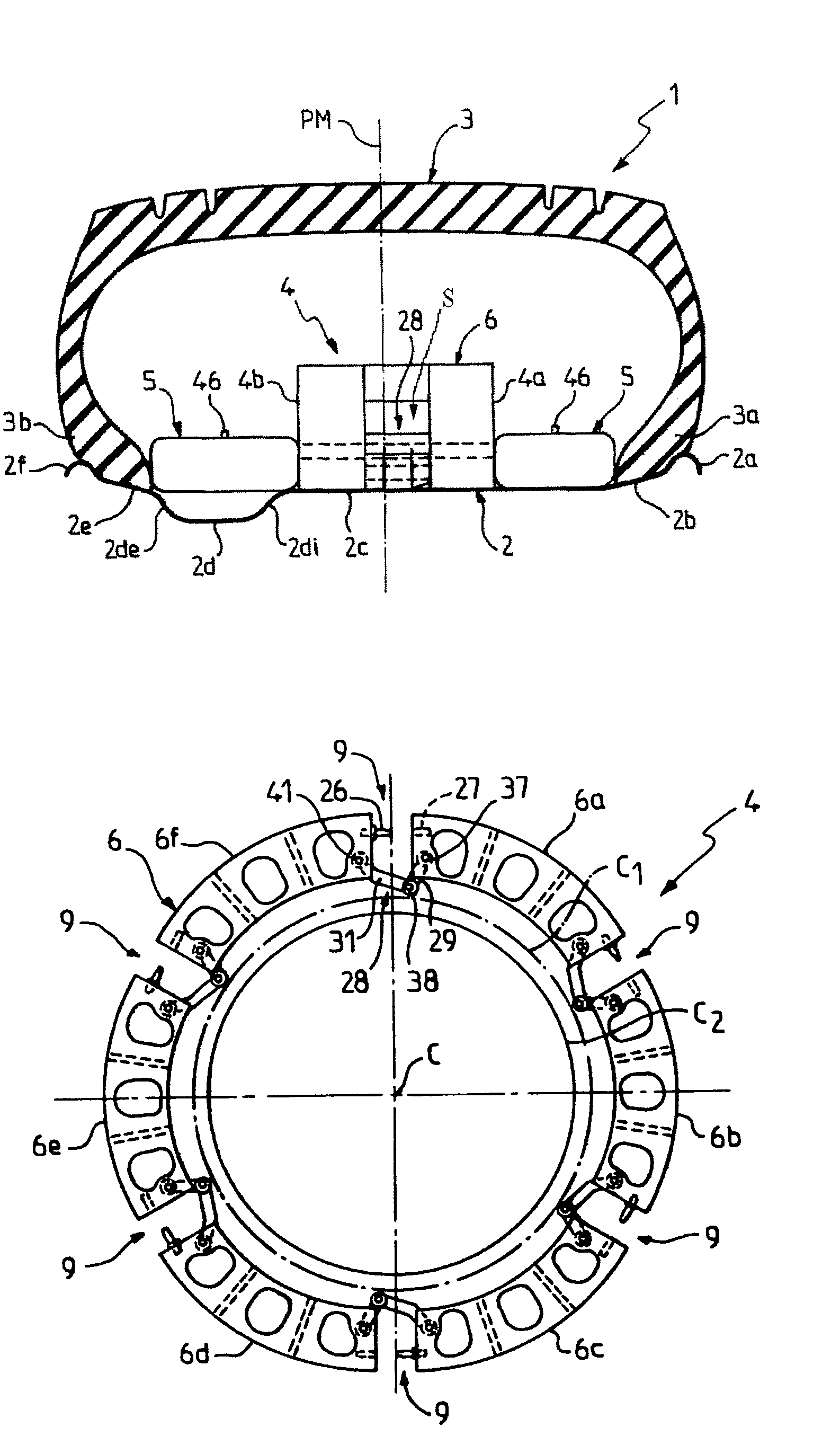
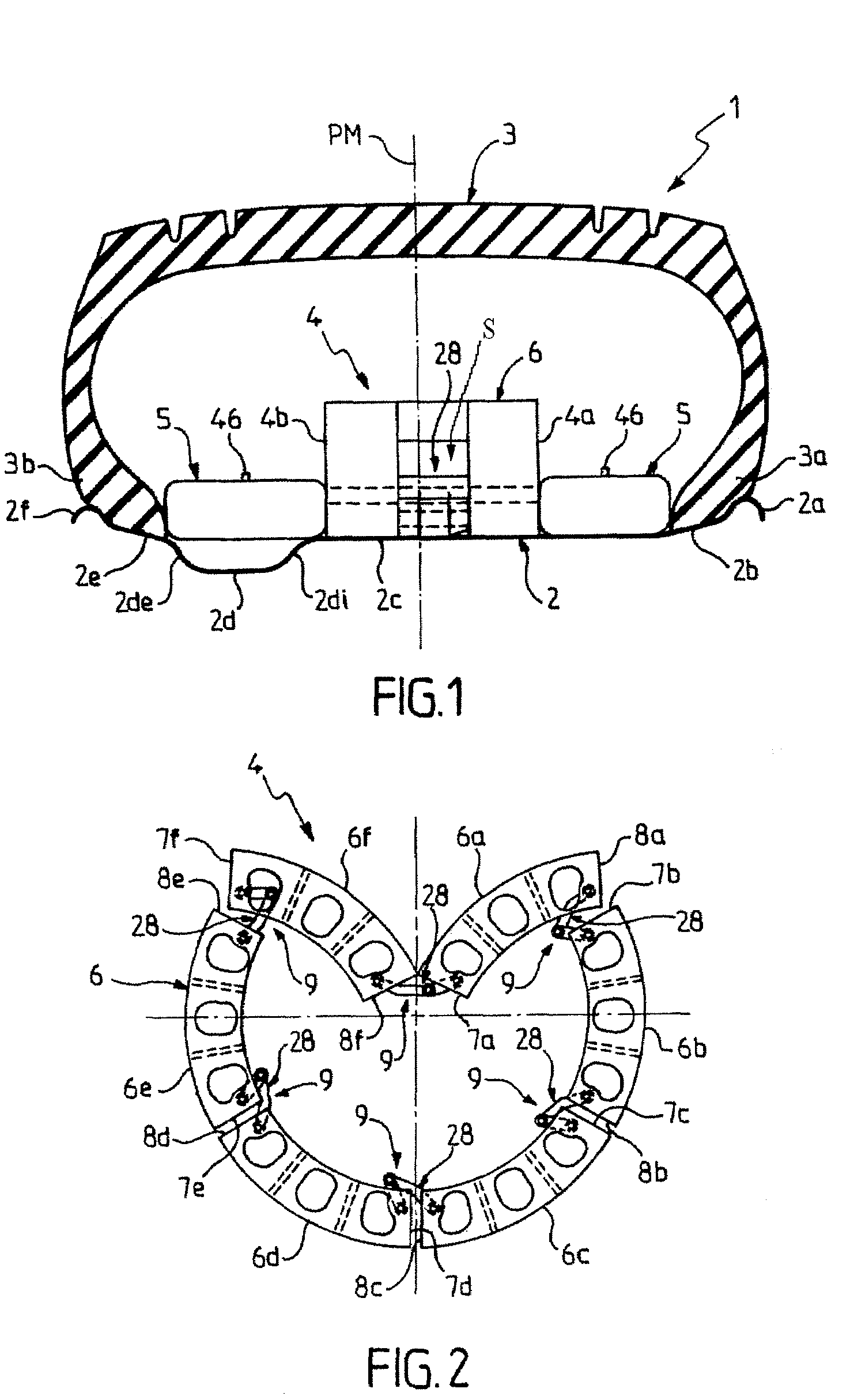
[0049]With reference to FIG. 1, it shows in axial section or meridian section a vehicle wheel 1 comprising a rim 2 onto which are mounted a tire 3 and a safety support 4.

[0050]In FIG. 1 (similarly in FIGS. 18, 20 and 23), the right side of the figure corresponds to the inner side of the wheel 1, that is the side which, in service, faces the body of the vehicle, while the left side of the figure corresponds to the outer side of the wheel 1, that is the side that faces the outside of the vehicle.

[0051]The rim 2 represented in FIG. 1 has a usual rim profile which comprises successively from the inner side to the outer side, that is from the right side to the left side of the figure, a hook-shaped inner edge 2a, an inner seat 2b for the inner bead 3a of the tire 3, a portion 2c, cylindrical or substantially cylindrical, that supports the safety support 4, a mounting well 2d whose inner side 2di connects smoothly to the portion 2c and whose outer side 2de connects to a seat 2e for the ou...


PUM


Abstract

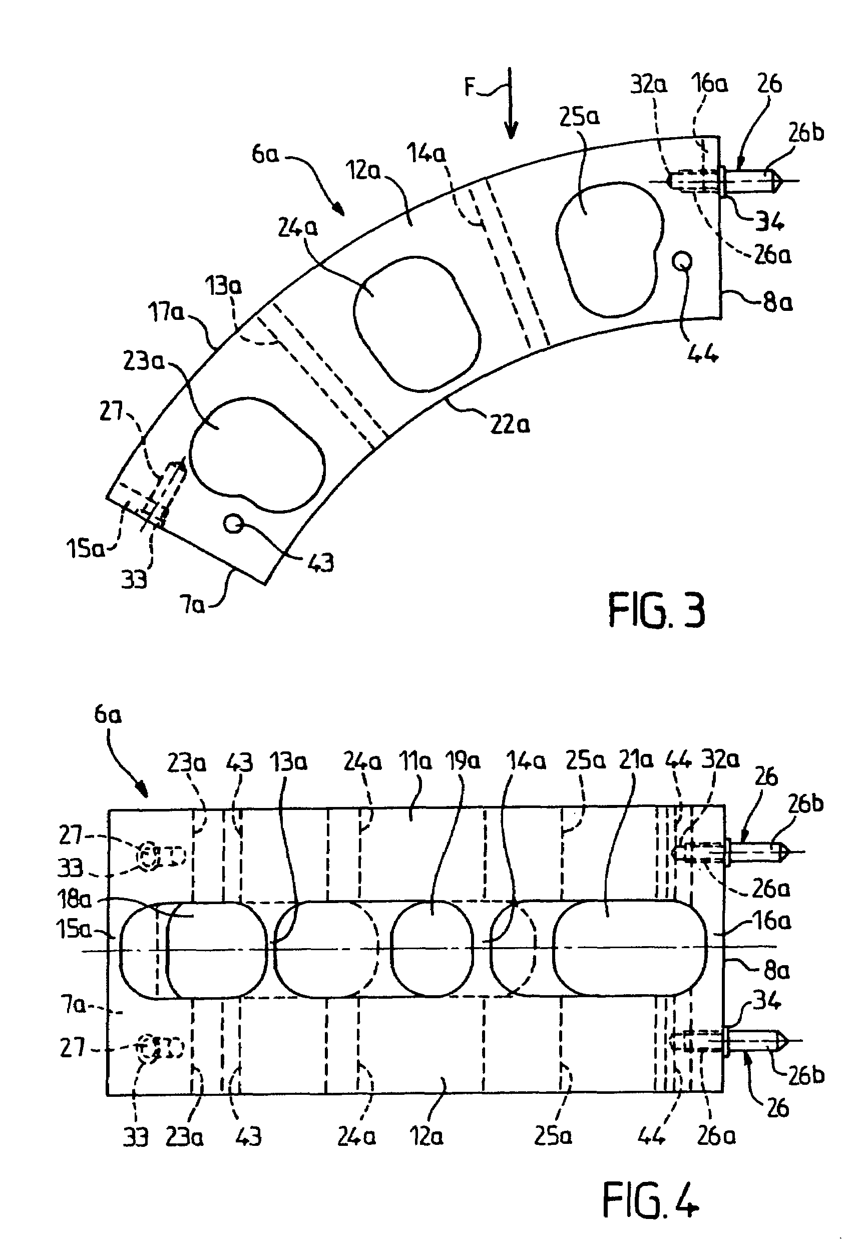
In this safety support comprising a segmented ring (6), whose segments (6a, . . . , 6f) are connected by linking means (9), at least one of the linking means (9) comprising at least one male element (26) and at least one female portion (27) suitable for fitting one inside the other by a relative movement of two segments in the circumferential direction of the ring, the at least one linking means (9) also comprises a lever mechanism (28) comprising at least two link arms (29, 31) of different lengths articulated on one another and each at one respective end of the two segments so that the lever mechanism acts so as to bring the two segments closer to one another when the male element (26) is partially engaged in the female portion (27) and when an articulation (38) common to two link arms of the lever mechanism (28) is moved substantially radially relative to the center (C) of the ring (6) in response to an axial movement of the ring relative to the rim.

Description

CROSS-REFERENCE TO RELATED APPLICATIONS[0001]This application claims the benefit of French Patent Application No. 04 / 04208, filed Apr. 21, 2004, which is incorporated herein by reference in its entirety.BACKGROUND OF THE INVENTION[0002]1. Field of the Invention[0003]The present invention relates to a safety support for a vehicle wheel, that is a support used to support at least partially a tire tread in conditions of low or zero pressure.[0004]2. Description of Related Art[0005]The present invention more particularly relates to a safety support of the type comprising a ring which is intended to be mounted on a rim of a wheel inside a tire and which is subdivided into at least two arced segments having ends which face one another, and several linking means which each connect two ends facing one another of two segments of the ring, at least one of the linking means comprising at least one male element at an end of one segment and at least one female portion at an end of another segmen...

Claims


Application Information

Patent Timeline
Patent Type & Authority Patents(United States)
IPC IPC(8): B60C17/00B60C15/032B60C17/04B60C17/06
CPCB60C15/032B60C17/041B60C17/06B60C17/04
Inventor CLOUET, ALAIN
Owner MICHELIN & CO CIE GEN DES ESTAB MICHELIN
Learn More