
Flat panel detector with KV/MV integration

Inactive Publication Date: 2007-08-28
SIEMENS MEDICAL SOLUTIONS USA INC
View PDF5 Cites 49 Cited by
  • Summary
  • Abstract
  • Description
  • Claims
  • Application Information

AI Technical Summary

Problems solved by technology

However, this configuration requires two photodetector assemblies (one for each radiation detector), and all of the associated hardware and electronics necessary for operating them.

Method used


Image

  • Flat panel detector with KV/MV integration
  • Flat panel detector with KV/MV integration
  • Flat panel detector with KV/MV integration

Examples


Embodiment Construction

[0015]Reference will now be made in detail to the presently preferred embodiments of the invention, examples of which are illustrated in the accompanying drawings.

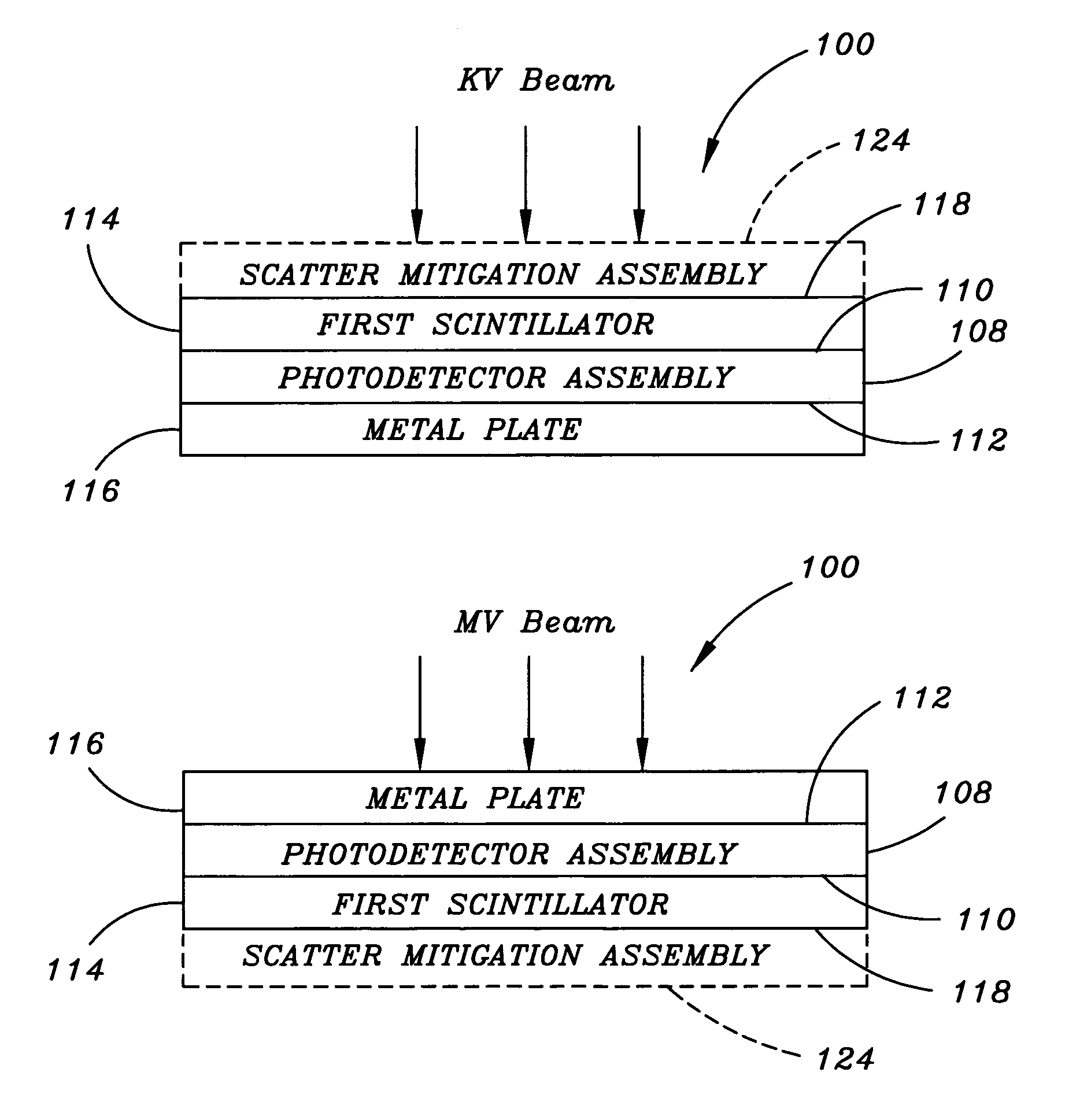
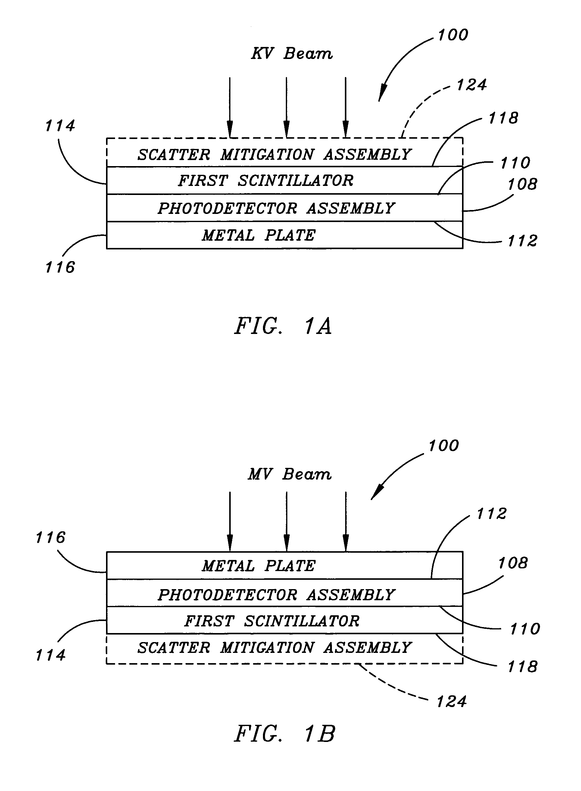
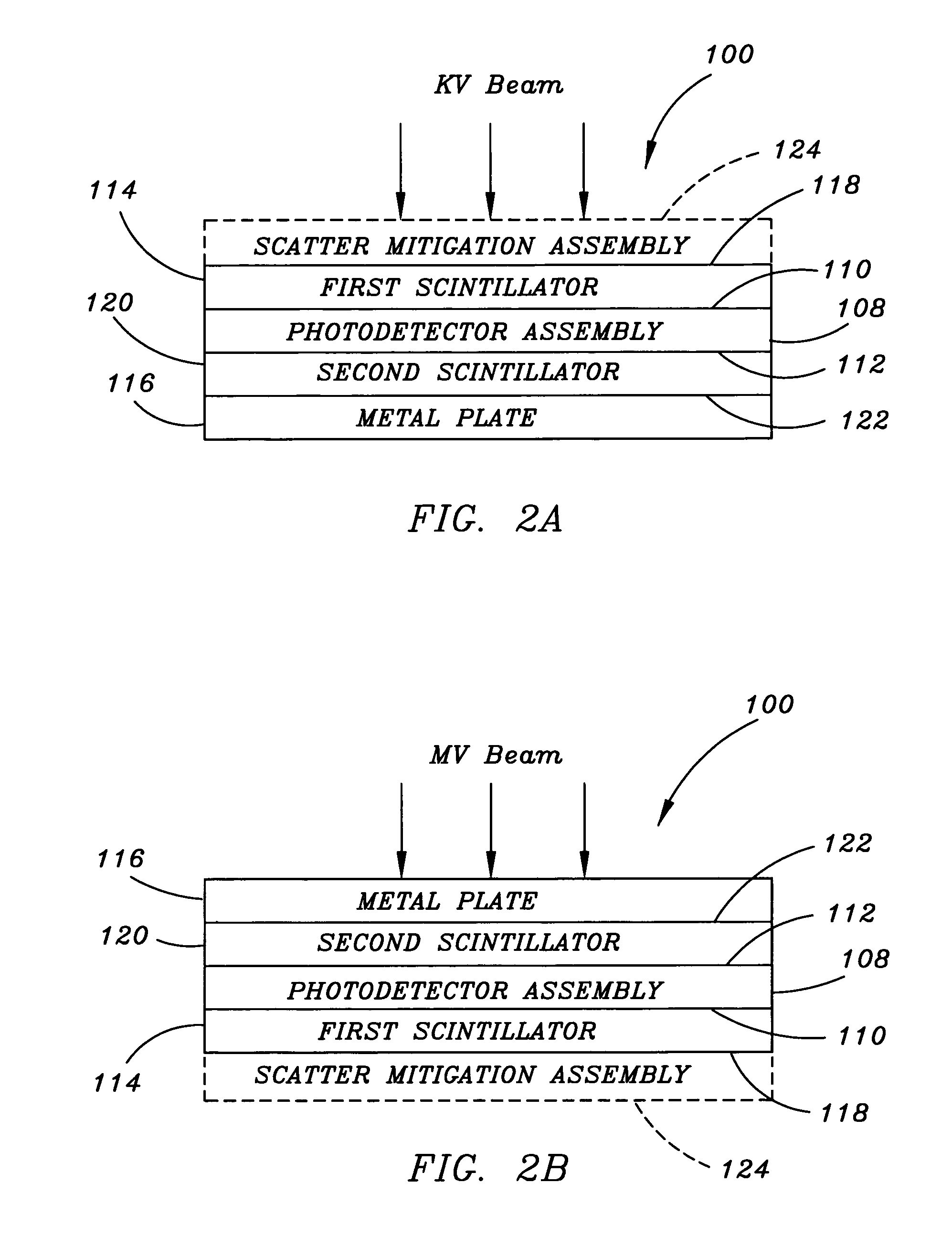
[0016]Referring to FIGS. 1A through 3B, a flat panel detector 100 for a radiation imaging device, such as a radiation imaging device 102 utilized for Image Guided Radiation Therapy (IGRT), or the like, is described in accordance with exemplary embodiments of the present invention. The detector 100 may be utilized for detecting radiation from a radiation source after the radiation has passed through an object being imaged, such as a human body, or the like.

[0017]The radiation imaging device 102 includes a KV radiation source 104 for providing KV imaging and an MV radiation source 106 for providing MV imaging. The detector 100 includes a photodetector assembly 108 for detecting light, such as a burst of luminescence emitted by scintillation material along the path of a high energy particle, or the like. For example, in one e...


PUM

PropertyMeasurementUnit
energyaaaaaaaaaa
distanceaaaaaaaaaa
KV imagingaaaaaaaaaa

Abstract

A radiation imaging device includes a detector capable of detecting radiation from either a KV source or an MV source. The detector includes a photodetector assembly, a scintillator adjacent to a first side of the photodetector, and a metal plate adjacent to a second side of the photodetector. The detector may also include a second scintillator. The first side of the photodetector assembly is positioned toward the KV source for KV imaging, while the second side is positioned toward the MV source for MV imaging. The radiation imaging device includes a first gantry for the MV source and a second gantry for the detector. The KV source may be supported by either the first gantry or the second gantry. The second gantry includes a robotic arm for positioning the detector for imaging, and is configured for moving the detector (and the KV source) out of the MV beam.

Description

BACKGROUND OF THE INVENTION[0001]The present invention relates generally to the field of radiation imaging devices, and more particularly to a flat panel detector providing Kilovolt / Megavolt (KV / MV) integration for radiation imaging devices capable of both KV imaging and MV imaging, particularly radiation imaging devices suitable for use in providing Image Guided Radiation Therapy (IGRT).[0002]IGRT uses patient positioning devices and radiation imaging to target and treat cancerous tumors more precisely. Prior to the use of IGRT, radiation oncologists contended with variations in patient positioning, including variations caused by a patient's respiratory motion. Inevitably, a margin of healthy tissue around a treatment site was treated with radiation. However, the use of IGRT allows a radiation oncologist to determine the exact positioning of a treatment site before the administration of radiation. IGRT combines three-dimensional radiation imaging technologies including X-ray volume...

Claims


Application Information

Patent Timeline
Patent Type & Authority Patents(United States)
IPC IPC(8): H05G1/64G01N23/04
CPCA61N5/1049G01T1/2018A61N2005/1054A61N2005/1061G01T1/20187
Inventor GHELMANSARAI, FARHAD
Owner SIEMENS MEDICAL SOLUTIONS USA INC
Learn More