
Protected cabinet

a cabinet and protection technology, applied in the field of protection cabinets, can solve the problems of limiting the access of the robber, affecting the service life of the bank, and affecting the satisfaction of bank employees or customers,

Inactive Publication Date: 2007-08-28
WEINBERGER YOAV
View PDF20 Cites 25 Cited by
  • Summary
  • Abstract
  • Description
  • Claims
  • Application Information

AI Technical Summary

Benefits of technology

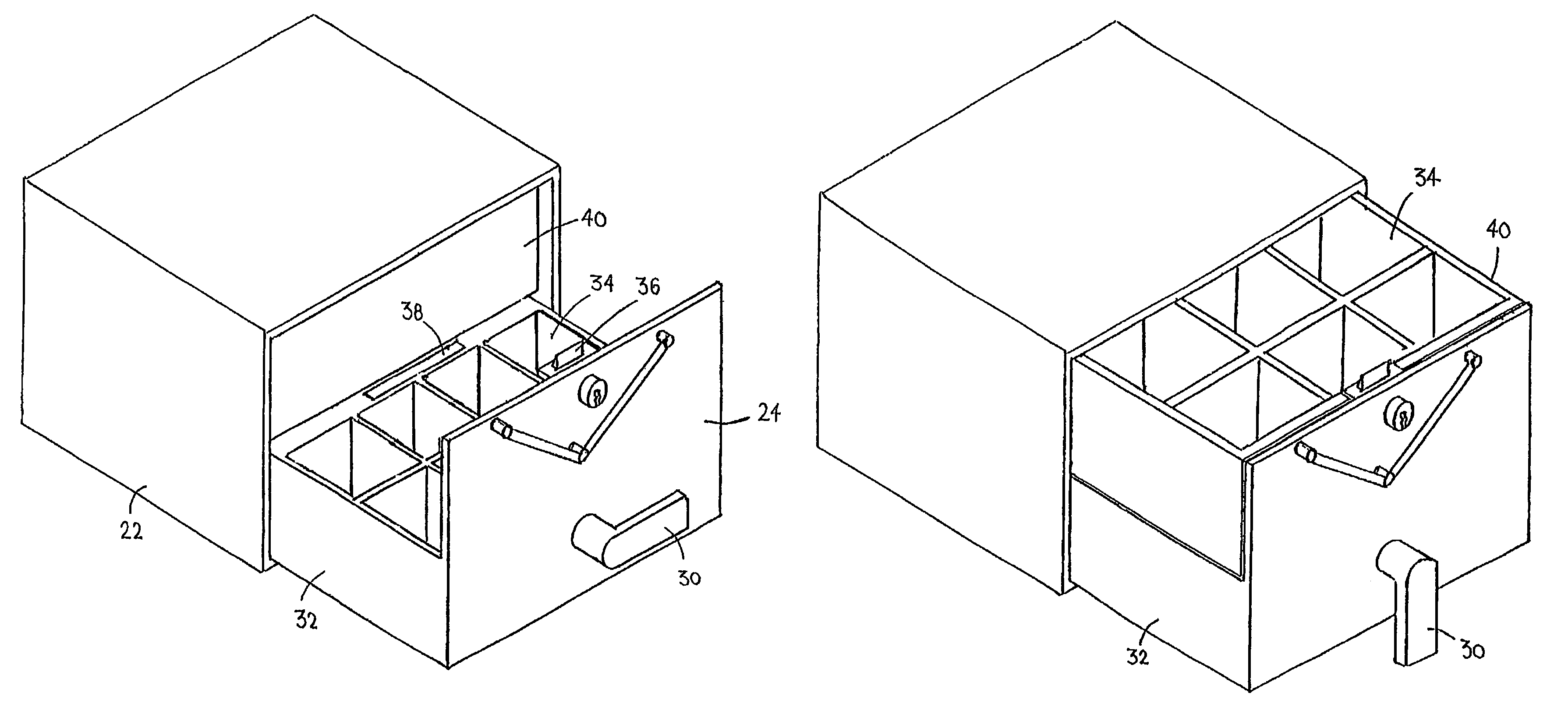
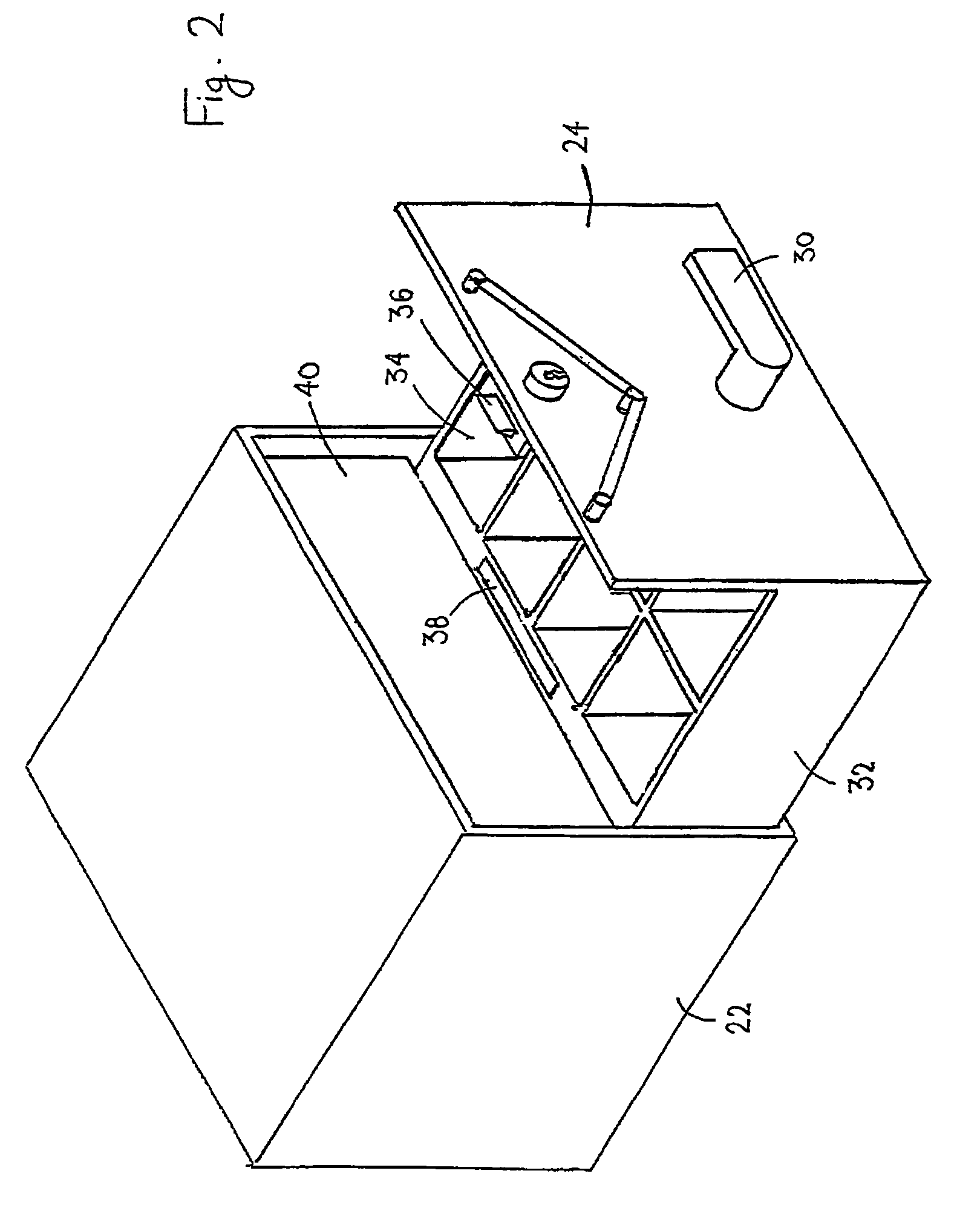
[0022]Furthermore, in accordance with a preferred embodiment of the present invention, the first drawer has a back portion normally hidden within the housing, and provided with a latching mechanism that in a first state prevents fully withdrawing the first drawer, keeping the hidden portion inside the housing, and in a second state releases the hidden portion to be withdrawn and exposed out of the housing.
[0023]Furthermore, in accordance with a preferred embodiment of the present invention, the latching mechanism comprising a lever pivotally connected to a partition defining the hidden portion, the lever coupled to an arm having a wedge, so that when the lever is pressed the wedge is lifted over a ligule provided at the bottom of the housing 22, making the withdrawal and exposure of the hidden compartment possible.
[0024]Furthermore, in accordance with a preferred embodiment of the present invention, second drawer is prevented from opening when the first drawer is opened, by means of a stopper mechanism.

Problems solved by technology

Most of these methods impose obstructions on the robbers, and thus may cause the robbers to panic, or enrage them, leading to unnecessary violence or even casualties.
Methods and devices limiting the robber's access to his desired catch—money found in teller cabinets or safes, is dangerous, for the frustrated robber may take out his frustration on bank employees or customers.

Method used


Image

  • Protected cabinet
  • Protected cabinet
  • Protected cabinet

Examples


Embodiment Construction

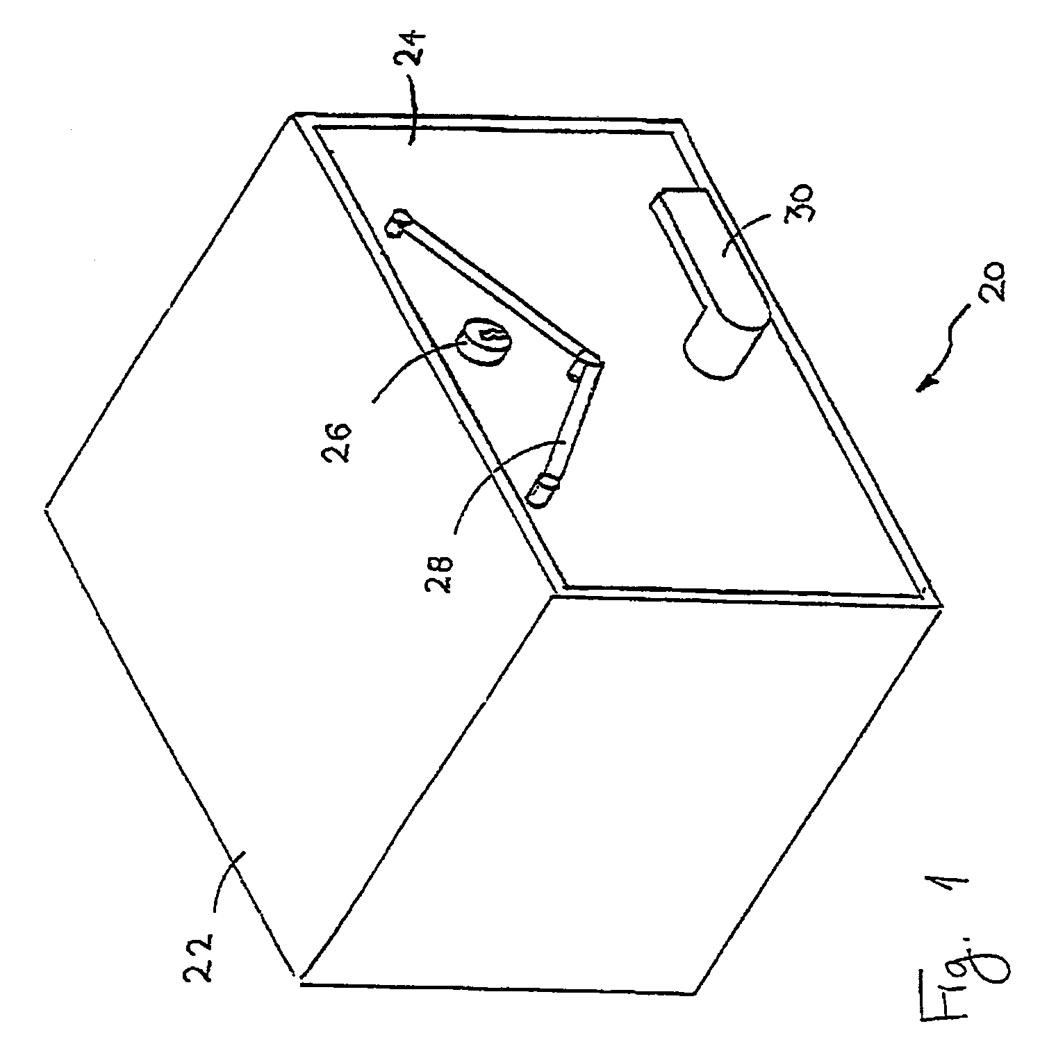
[0049]The protected cabinet of the present invention is aimed at providing a secured cabinet for cash and other valuables, for use by a public service provider, such as a bank teller (hereinafter referred to as “a teller”).

[0050]An aspect of the present invention is the provision of a regular drawer and an emergency drawer in the cabinet. Under regular circumstances, the regular drawer is used by the teller for transactions carried our during then regular course of business. When an emergency situation, namely a robbery, occurs, the teller switches to the emergency drawer, that contains some money and hands it to the robber to appease him, making him believe he got all the content of the cash drawer (the fact that there are two drawers in the cabinet is of course kept a as secret and not revealed to the public).

[0051]Another aspect of the present invention is the provision of such protected cabinet with safety means aimed at preventing opening of the emergency drawer when the regula...


PUM


Abstract

A protected cabinet for cash or other valuables, designed to protect the cash or valuables from being robbed, the protected cabinet comprising: a housing, for receiving and housing two drawers, having a front opening through which one or both drawers simultaneously may be withdrawn; a first drawer, adapted to be moved into and out of the housing through the front opening, coupled to a front panel, the front panel adapted to substantially cover the front opening of the housing; a second drawer, positioned over the first drawer, adapted to be moved into and out of the housing through the front opening, when engaged to the first drawer, substantially covering the first drawer when engaged to it, preventing view of contents of the first drawer; engagement mechanism for engaging the second drawer to the first drawer, whereby one drawer is regularly used for transactions or presentation of the cash or valuables kept in it, whereas the other drawer is used as an emergency, decoy, drawer, pulled open in emergency instances, such as in a robbery, by operating the engagement mechanism.

Description

CROSS-REFERENCE TO RELATED APPLICATIONS[0001]This application is a National Phase Application of PCT International Application No. PCT / IL02 / 00802, International Filing Date Oct. 2, 2002, claiming priority of Israel Patent Applications, 147324, filed Dec. 26, 2001, and 148005, filed Feb. 5, 2002.FIELD OF THE INVENTION[0002]The present invention relates to protection from robbery or theft. More particularly, the present invention relates to a protected cabinet for cash or other items of value.BACKGROUND OF THE INVENTION[0003]Various methods of protection against robberies were developed over the years. Some of these methods include, forced delays before a safe door can be opened, doors locking when an emergency button is hit, silent alarm button, hidden beneath the desk, actuated to notify the police a robbery is in progress, etc.[0004]Most of these methods impose obstructions on the robbers, and thus may cause the robbers to panic, or enrage them, leading to unnecessary violence or e...

Claims


Application Information

Patent Timeline
Patent Type & Authority Patents(United States)
IPC IPC(8): A47B88/04A47B67/04A47B88/00A47B88/80E05G1/00E05G5/00G07F9/06G07G1/00H05K5/02
CPCA47B67/04A47B88/02E05G5/006G07F9/06G07G1/0027E05Y2900/20A47B88/70
Inventor WEINBERGER, YOAV
Owner WEINBERGER YOAV
Learn More