
System for transmitting video images over a computer network to a remote receiver

a video image and computer network technology, applied in the field of video communication systems, can solve problems such as unnecessarily treating patients, wrong diagnosis, and catastrophic for patients, and achieve the effects of reducing the number of patients

Inactive Publication Date: 2007-08-14
SECURE CAM LLC
View PDF59 Cites 107 Cited by
  • Summary
  • Abstract
  • Description
  • Claims
  • Application Information

AI Technical Summary

Benefits of technology

[0007]A method of and apparatus for transmitting video images preferably allows a specially trained individual to remotely supervise, instruct, and observe administration of medical tests conducted at remote locations. This apparatus preferably includes a source device, a transmitting device, and at least one remote receiving device. Preferably, the transmitting device and the remote receiving device communicate over a network such as the Internet Protocol network. Alternatively, the transmitting device and the receiving device communicate over any appropriate data network. The transmitting device transmits the video images to the remote receiving device either for live display through the source device or for pre-recorded display through a video recorder device. The remote receiving device is also capable of communicating with the transmitting device while simultaneously receiving video images. The source device is preferably a medical test device such as an ultrasound, a sonogram, an echocardiogram, an angioplastigram, and the like. This medical test device preferably generates video images for the transmitting device. The transmitting device captures the video images in real-time from the source device and compresses these video images utilizing a compression algorithm prior to transmitting data representing the video images to the remote receiving device. Remote users utilizing the remote receiving devices are capable of remotely controlling a number of parameters relating to the source device and the transmitting device. Such parameters include image quality, storage of the video images on the transmitting device, manipulating and controlling the source device, and the like.

Problems solved by technology

While these tools allow doctors to make their diagnosis without costly, risky, and time consuming exploratory surgeries, an error in administering an ultrasound, sonogram, echocardiogram, and angioplastigram can lead to a wrong diagnosis.
A wrong diagnosis can be catastrophic for the patient.
By receiving an incorrect diagnosis, the patient can potentially fail to receive needed medical treatment and / or be unnecessarily treated.
Whether needed medical treatment is withheld or unnecessary medical treatment is given due to an erroneous test result from an ultrasound, sonogram, echocardiogram, or angioplastigram, the patient unnecessarily suffers.
While ultrasounds, sonograms, echocardiograms, and angioplastigrams are extremely useful tools to diagnose ailments in patients, any of these tools administered in an imprecise manner or in a wrong location will most likely produce a wrong result.
This wrong result typically leads to the wrong diagnosis.
Instead, technicians with limited medical knowledge and limited training typically administer these tests.
By not properly administering these tests, the results are often times inaccurate and lead to the wrong diagnosis.
However, having such a specially trained person at each of these tests while they are being administered is typically impractical and would result in much higher medical costs.

Method used


Image

  • System for transmitting video images over a computer network to a remote receiver
  • System for transmitting video images over a computer network to a remote receiver
  • System for transmitting video images over a computer network to a remote receiver

Examples


Embodiment Construction

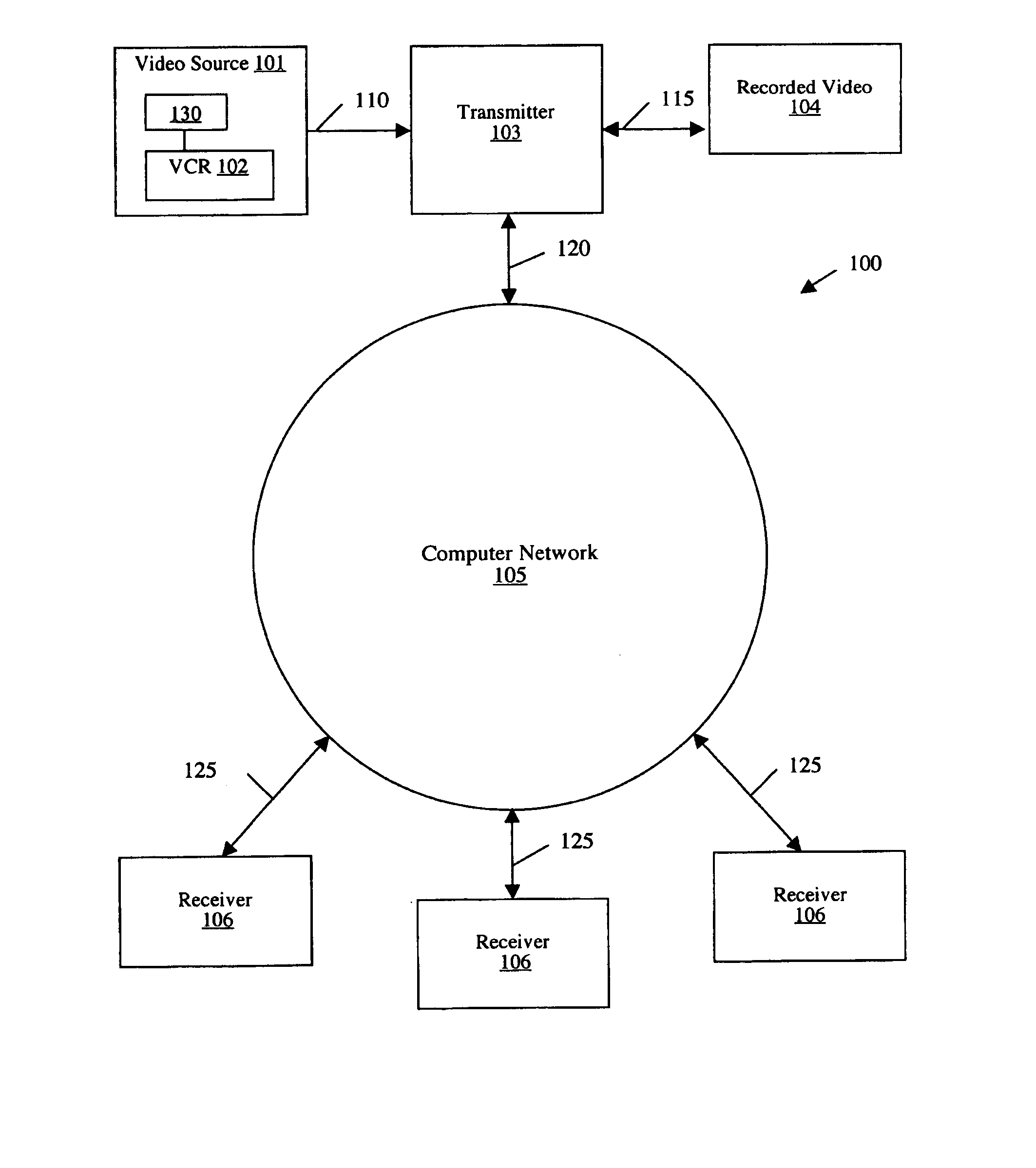
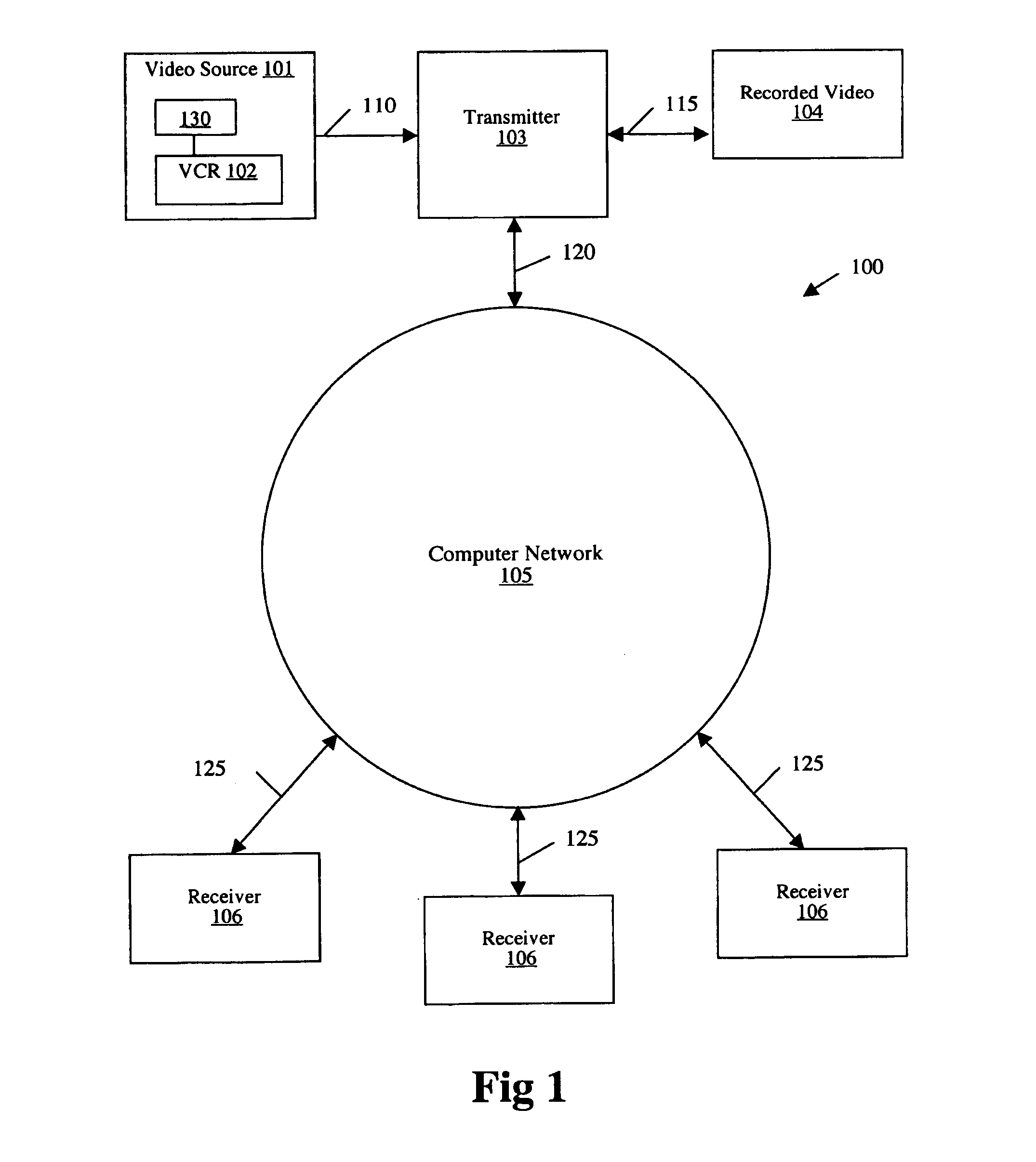
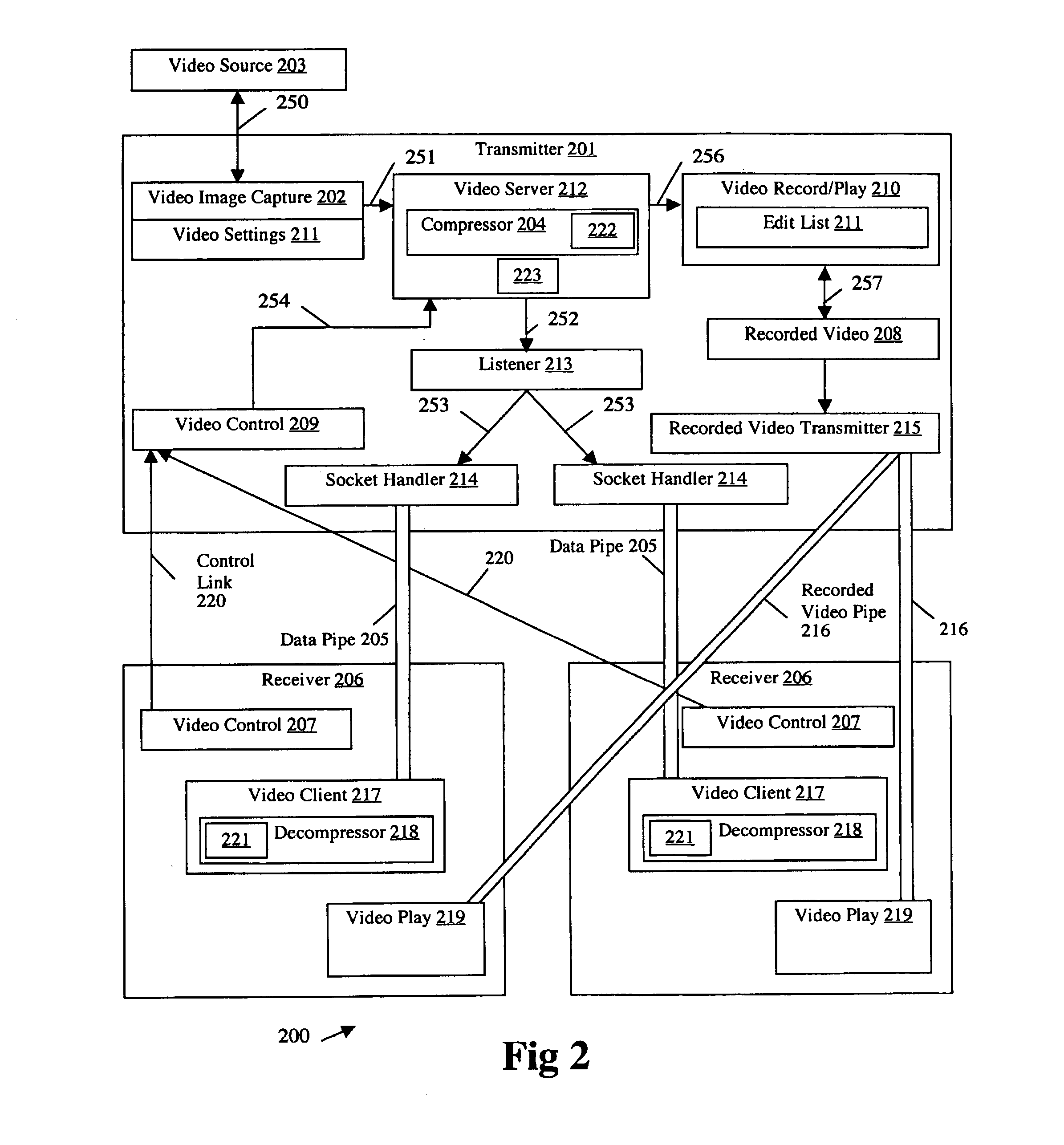
[0023]FIG. 1 illustrates a video system 100 according to the present invention for transmitting video images from one location to another. The video system 100 preferably includes a video source 101, a video cassette recorder 102, a transmitter 103, a recorded video device 104, a computer network 105, a plurality of receivers 106, and data links 110, 115, 120, and 125. Preferably, the video source 101 includes the video cassette recorder 102 and is coupled to the transmitter 103 via the data link 110. The data link 110 is preferably a Super-Video (S-Video) connection. The transmitter 103 is also preferably coupled to the recorded video device 104 and the computer network 105 via the data links 115 and 120, respectively.

[0024]Preferably, the plurality of receivers 106 are coupled to the computer network 105 via the data links 125. Each of the plurality of receivers 106 are preferably a computer system having a display, central processing unit, and input device. The data links 125 pre...


PUM


Abstract

A method of and apparatus for transmitting video images preferably allows a specially trained individual to remotely supervise, instruct, and observe administration of medical tests conducted at remote locations. This apparatus preferably includes a source device, a transmitting device, and at least one remote receiving device. Preferably, the transmitting device and the remote receiving device communicate over a network such as the Internet Protocol network. Alternatively, the transmitting device and the receiving device communicate over any appropriate data network. The transmitting device transmits the video images to the remote receiving device either for live display through the source device or for pre-recorded display through a video recorder device. The remote receiving device is also capable of communicating with the transmitting device while simultaneously receiving video images. The source device is preferably a medical test device such as an ultrasound, a sonogram, an echocardiogram, an angioplastigram, and the like. This medical test device preferably generates video images for the transmitting device. The transmitting device captures the video images in real-time from the source device and compresses these video images utilizing a compression algorithm prior to transmitting data representing the video images to the remote receiving device. Remote users utilizing the remote receiving devices are capable of remotely controlling a number of parameters relating to the source device and the transmitting device. Such parameters include image quality, storage of the video images on the transmitting device, manipulating and controlling the source device, and the like.

Description

RELATED APPLICATIONS[0001]This application claims priority under 35 U.S.C. § 119(e) of the co-pending U.S. provisional application Ser. No. 60 / 085,818 filed on May 18, 1998 and entitled “APPARATUS FOR TRANSMITTING LIVE VIDEO IMAGES OVER A COMPUTER NETWORK TO MULTIPLE REMOTE RECEIVERS.” The provisional application Ser. No. 60 / 085,818 filed on May 18, 1998 and entitled “APPARATUS FOR TRANSMITTING LIVE VIDEO IMAGES OVER A COMPUTER NETWORK TO MULTIPLE REMOTE RECEIVERS” is also hereby incorporated by reference.FIELD OF THE INVENTION[0002]This invention relates to the field of communications systems. More particularly, this invention relates to the field of video communications systems.BACKGROUND OF THE INVENTION[0003]In the last decade, there have been tremendous advances in medical devices which have greatly improved the ability to diagnose and treat patients. Ultrasounds, sonograms, echocardiograms, and angioplastigrams are just a few modern tools developed to accurately diagnose patie...

Claims


Application Information

Patent Timeline
Patent Type & Authority Patents(United States)
IPC IPC(8): H04B1/66A61B8/00
CPCH04N19/70A61B8/565H04N19/90
Inventor FIGUEREDO, VINCENT MICHAELROMAN, KENDYL ALLANRAPOSO, R. PAULNEALE, RICHARD SCOTTHOOMANI, CYRUS JAVADBROADBENT, THOMAS JOSEPH
Owner SECURE CAM LLC
Learn More