Connection terminal and a connection terminal assembly and method for assembling the connection terminal
a technology of connection terminals and assembly methods, applied in the direction of incorrect coupling prevention, coupling device connection, electrical apparatus, etc., can solve the problems of increasing cost, complex assembly process, and difficulty in positioning the terminal, so as to avoid the increase in cost and facilitate positioning
- Summary
- Abstract
- Description
- Claims
- Application Information
AI Technical Summary
Benefits of technology
Problems solved by technology
Method used
Image
Examples
embodiment 1
[0051]Embodiments of the present invention will be explained below with reference to the drawings. Firstly, an embodiment 1 will be explained with reference to FIGS. 1 to 19. FIG. 1 is a local sectional view of a brake device using a connection terminal according to the present invention. The brake device employs a hydraulic circuit housing 1 (a first housing, or simply, a housing), an electrical control unit (ECU) board 2 (a connected member) that faces hydraulic circuit housing 1, a male connector 100 (a first assembly), and a female connector 200 (a second assembly). In FIG. 1, a direction from hydraulic circuit housing 1 toward ECU board 2 (this direction is a connecting direction of a connection terminal in the present invention) is defined as z-axis, an axis orthogonal to z-axis and parallel to the drawing is defined as x-axis, and a direction normal to the drawing is defined as y-axis.
[0052]Hydraulic circuit housing 1 is formed by aluminum die casting. And a hydraulic circuit...
case 140
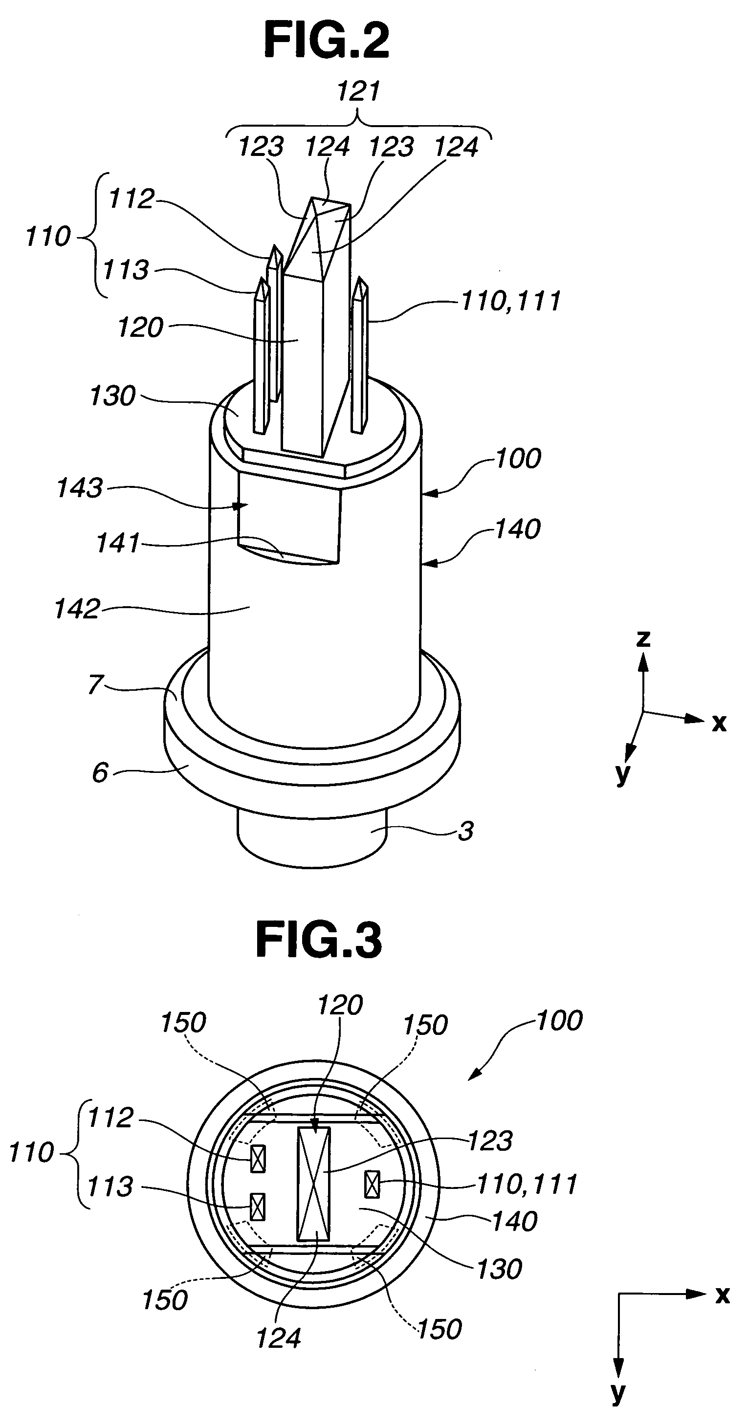
[0067]Case 140, which is substantially cylindrical in shape, has a step or stepped portion 141 (a limiting or limitation portion that limits movement in a terminal stage installation direction of terminal stage 130) at an upper end portion (or positive direction side end portion) in z-axis direction of case 140. Further, case 140 has a cylindrical portion 142 that is positioned below the stepped portion 141, and a hollow elongated hole portion 143 that is positioned above the stepped portion 141. Cylindrical portion 142 is substantially cylindrical in shape. As for hollow elongated hole portion 143, it is elongated hole in shape, which is cut off at circumferentially-opposed arcs of case 140 along z-axis direction in the same manner as projecting portion 132 of terminal stage 130. And an opening portion 145 of hollow elongated hole portion 143 is opened in the positive direction of z-axis as being the shape. That is to say, case 140 is formed of stepped portion 141, cylindrical port...
embodiment 4
[0109]In the embodiment 4, guide 120′ of male connector 100′ is formed into cylindrical shape. Male terminal 110′ is also formed into cylindrical shape. Further, male terminal 110′ tapers to a point at the top. At periphery of terminal stage 130′, as shown in FIG. 27, a rotation stopper receiving portion 133′ is provided as an anti-rotation mechanism. This rotation stopper receiving portion 133′ is formed by cutting away circumferentially-opposed arcs of outer periphery of terminal stage 130′ from the positive direction of z-axis such that rotation stopper receiving portion 133′ is recessed radially inward and downward.
[0110]Although the detail of the anti-rotation mechanism will be explained later, the rotation of a certain rotation amount or more of terminal stage 130′ is limited by means of rotation stopper receiving portion 133′ and a rotation stopper portion 141′ (see FIGS. 29, 30) that is provided for a case 140′. Here, in this embodiment, two rotation stopper receiving portio...
PUM
 Abstract
Description
Claims
Application Information
 - R&D
- Intellectual Property
- Life Sciences
- Materials
- Tech Scout
- Unparalleled Data Quality
- Higher Quality Content
- 60% Fewer Hallucinations
Browse by: Latest US Patents, China's latest patents, Technical Efficacy Thesaurus, Application Domain, Technology Topic, Popular Technical Reports.
© 2025 PatSnap. All rights reserved.Legal|Privacy policy|Modern Slavery Act Transparency Statement|Sitemap|About US| Contact US: help@patsnap.com


