
Vehicle carrying rail road car and bridge plate therefor

a technology for rail road cars and bridge plates, applied in the field of rail road cars, can solve the problems of slow and less flexible highway operation of tofc, less efficient tofc service, and less efficient double-stack cofc service in which containers are transported

Inactive Publication Date: 2007-08-14
NATIONAL STEEL CAR
View PDF67 Cites 29 Cited by
  • Summary
  • Abstract
  • Description
  • Claims
  • Application Information

AI Technical Summary

Benefits of technology

The invention is a bridge plate that can be used to connect two rail cars together. The bridge plate can pivot on a vertical axis and also has a linear extension member that allows it to move on a second vertical axis. This allows for flexibility in the distance between the two vertical axes. The technical effect of this invention is to provide a reliable and flexible connection between two rail cars, even when they are not perfectly aligned.

Problems solved by technology

The technical problem addressed in this patent text is the need for a short-slip draft gear for vehicles that can accommodate high levels of impact and can reduce bumps and impact at the bridge plates. The text describes the use of a two-speed draft gear that can provide ultra-high levels of impact absorption and can also reduce the height of the bump at the bridge plate. The text also discusses the advantages and disadvantages of using monolithic beam and flared sills for forming bridge plates. The text also mentions the need for a rail roadcar that can be easily converted to a container or a trailer. The text also describes the use of short-slip buff plates and the importance of stay-in-place bridge plates in the context of the M-90 and M-91 vehicles. The text also discusses the use of low-slip buff plates for high-speed railcar applications. The text also mentions the need for a method to reduce the impact of the bump gear and the importance of employing monolithic end-cou plates for various sizes of vehicles and highway trailers.

Method used


Image

  • Vehicle carrying rail road car and bridge plate therefor
  • Vehicle carrying rail road car and bridge plate therefor
  • Vehicle carrying rail road car and bridge plate therefor

Examples


Embodiment Construction

[0092]The description that follows, and the embodiments described therein, are provided by way of illustration of an example, or examples of particular embodiments of the principles of the present invention. These examples are provided for the purposes of explanation, and not of limitation, of those principles and of the invention. In the description, like parts are marked throughout the specification and the drawings with the same respective reference numerals. The drawings are not necessarily to scale and in some instances proportions may have been exaggerated in order more clearly to depict certain features of the invention.

[0093]In terms of general orientation and directional nomenclature, for each of the rail road cars described herein, the longitudinal direction is defined as being coincident with the rolling direction of the car, or car unit, when located on tangent (that is, straight) track. In the case of a car having a center sill, whether a through center sill or stub sil...


PUM


Abstract

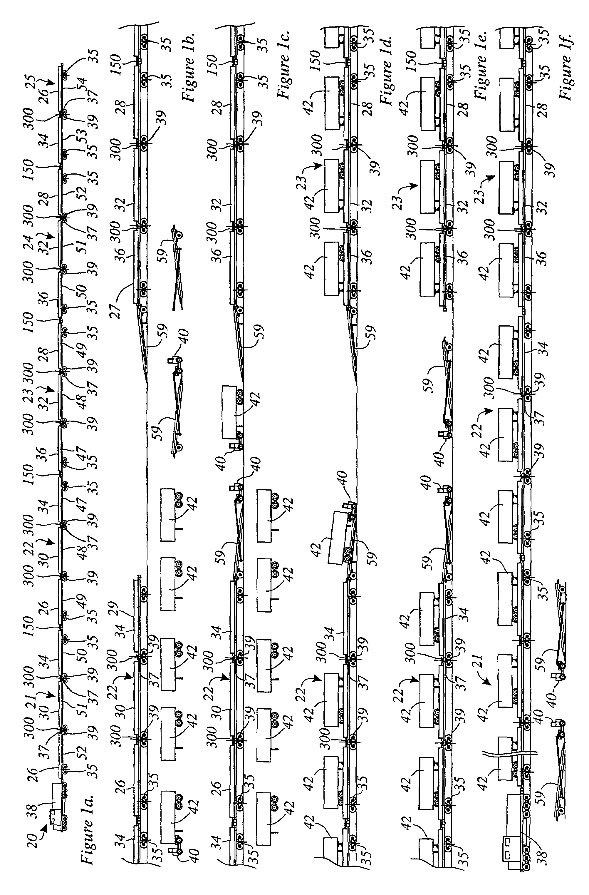
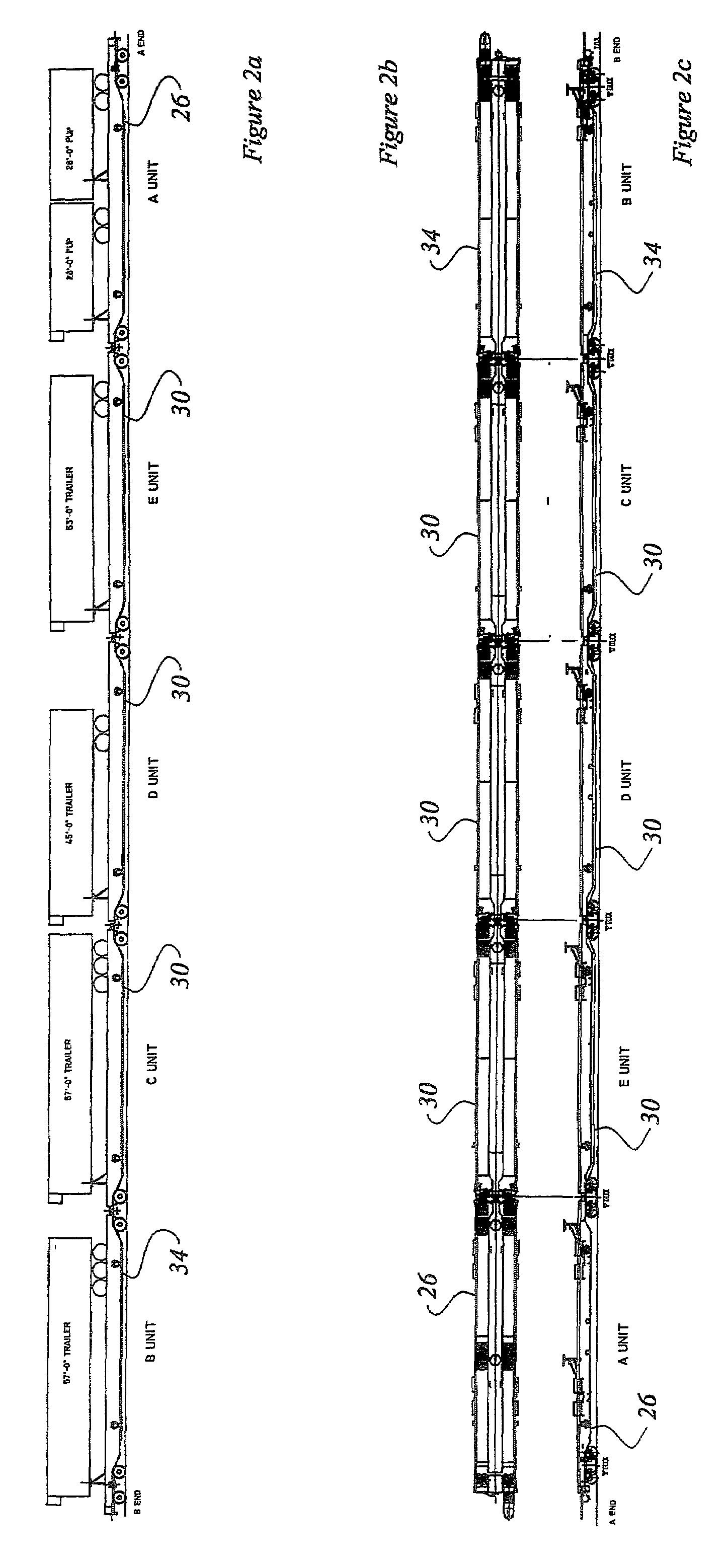
A rail road car has a deck for carrying wheeled vehicles. The rail road car can be coupled to other rail road cars of the same type. Bridge plates are provide that permit wheeled vehicles to be conducted between adjacent rail road cars. The bridge plates have one end mounted to the rail road car at a pivot fitting. The pivot fitting allows the bridge plate to be moved from a length-wise position spanning the gap between cars, to a cross-wise stowed position. The bridge plates have fittings which permit three degrees of freedom relative to the adjacent rail road cars, namely a first degree of freedom to tolerate yawing motion of the first rail road car, a second degree of freedom to accommodate yawing motion of the second rail road car, and a third degree of freedom to accommodate variation in distance between the respective portions of the rail road cars to which the bridge plate is mounted while the rail road cars are moving.

Description


Claims


Application Information

Patent Timeline
Owner NATIONAL STEEL CAR
Learn More