Safety valve lock out system and method

a safety valve and lockout technology, applied in the direction of fluid removal, wellbore/well accessories, construction, etc., can solve the problems of safety valve locking out permanently, control line used to operate the safety valve may develop a leakage or be severed, closure device of the safety valve may not close properly or seal adequately, etc., to achieve convenient, economical and effective manner

Inactive Publication Date: 2007-08-07
HALLIBURTON ENERGY SERVICES INC
View PDF4 Cites 1 Cited by
  • Summary
  • Abstract
  • Description
  • Claims
  • Application Information

AI Technical Summary

Benefits of technology

[0005]In carrying out the principles of the present invention, in accordance with an embodiment thereof, a safety valve lock out system and method are provided which prevent a safety valve from closing, and which do so in a convenient, economical and effective manner.
[0006]In one aspect of the invention, a method of locking out a safety valve in a subterranean well is provided. The method includes the steps of: flowing a hardenable fluid into the safety valve; and preventing a closure device of the safety valve from closing with the hardenable fluid.
[0007]In another aspect of the invention, a system for locking out a safety valve positioned in a subterranean well is provided. The system includes a container having a hardenable fluid therein, and a pump for transferring the hardenable fluid from the container to the safety valve. The hardenable fluid prevents a closure member of the safety valve from closing.

Problems solved by technology

Typically, a safety valve is locked out permanently due to a malfunction.
For example, a control line used to operate the safety valve may develop a leak or be severed, a flapper or other closure device of the safety valve may fail to close properly or seal adequately, etc.
Prior methods of locking out safety valves have required complex mechanisms to open and secure the closure device.

Method used


Image

  • Safety valve lock out system and method
  • Safety valve lock out system and method
  • Safety valve lock out system and method

Examples


Embodiment Construction

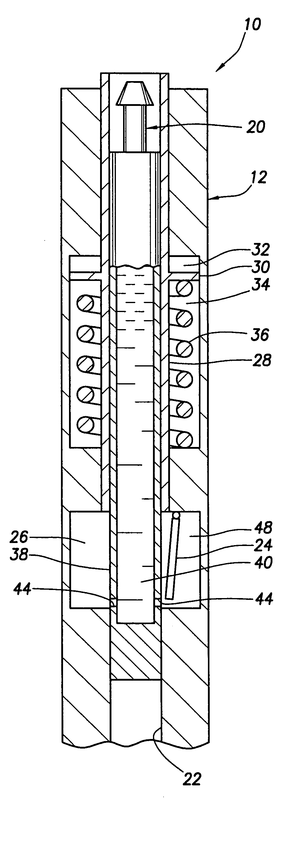
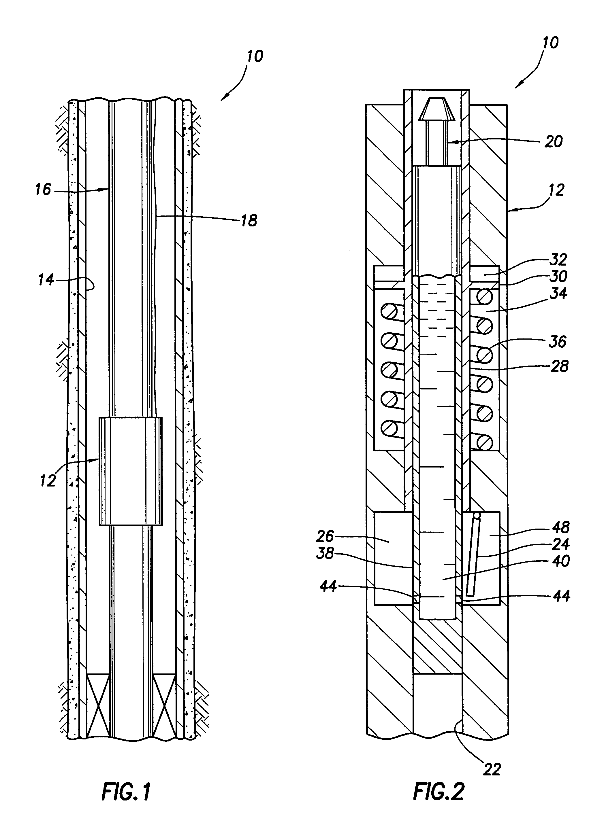
[0016]Representatively illustrated in FIG. 1 is a safety valve lock out system 10 which embodies principles of the present invention. In the following description of the system 10 and other apparatus and methods described herein, directional terms, such as “above”, “below”, “upper”, “lower”, etc., are used for convenience in referring to the accompanying drawings. Additionally, it is to be understood that the various embodiments of the present invention described herein may be utilized in various orientations, such as inclined, inverted, horizontal, vertical, etc., and in various configurations, without departing from the principles of the present invention.

[0017]As depicted in FIG. 1, a safety valve 12 is positioned in a wellbore 14 of a well. In this example, the safety valve 12 is interconnected in a tubular string 16, such as a production tubing string. This type of safety valve is known to those skilled in the art as a tubing retrievable safety valve. However, it should be clea...


PUM


Abstract

A safety valve lock out system and method. In a described embodiment, a method of locking out a safety valve in a subterranean well includes the steps of: flowing a hardenable fluid into the safety valve; and preventing a closure device of the safety valve from closing with the hardenable fluid.

Description

BACKGROUND[0001]The present invention relates generally to operations performed and equipment utilized in conjunction with a subterranean well and, in an embodiment described herein, more particularly provides a safety valve lock out system and method.[0002]It is sometimes desirable to lock out a safety valve, that is, to render the safety valve inoperative by preventing it from closing. Typically, a safety valve is locked out permanently due to a malfunction. For example, a control line used to operate the safety valve may develop a leak or be severed, a flapper or other closure device of the safety valve may fail to close properly or seal adequately, etc. A safety valve may be locked out temporarily, for example, to permit unobstructed workover operations through the safety valve.[0003]Prior methods of locking out safety valves have required complex mechanisms to open and secure the closure device. Some of these require an opening prong or flow tube of the safety valve to be displ...

Claims


Application Information

Patent Timeline
IPC IPC(8): E21B34/06E21B34/00E21B34/10
CPCE21B34/102E21B2034/005E21B2200/05
Inventor CROW, ROBERT W.
Owner HALLIBURTON ENERGY SERVICES INC
Why Eureka
Try Eureka