
Linear generator apparatus

a generator and line generator technology, applied in the direction of resilient suspensions, dynamo-electric machines, vehicle springs, etc., can solve the problems of inability to maximize, system presented does not seem to show, and energy recovery is optimized, so as to save gas consumption and brake wear. , the effect of saving energy

Inactive Publication Date: 2007-07-31
BEAULIEU GERALD
View PDF4 Cites 46 Cited by
  • Summary
  • Abstract
  • Description
  • Claims
  • Application Information

AI Technical Summary

Benefits of technology

[0007]An advantage of the present invention is that the linear generator apparatus provides for a system optimizing the recuperation of energy, or means to generate electrical power, based on road irregularities ranging preferably between about 0 mm and about 10 mm or a variety of high frequencies systems.
[0008]Another advantage of the present invention is that the linear generator apparatus provides for a helical spring or biasing means with one end enabled to move within a predetermined displacement range, and an urging means or compressive spring pushing or forcing back the biasing means towards the predetermined displacement range when limits are reached.
[0009]A further advantage of the present invention is that the linear generator apparatus can be adapted to various types of traffic vehicles or other equipments with an averaging high frequency in a preferred predetermined zone or free zone, i.e. a zone free of any biasing force counteracting the axial component of an induced vibration.
[0010]Still another advantage of the present invention is that the linear generator apparatus can be adapted into various types of vehicle frames.
[0011]Another advantage of the present invention is that the linear generator apparatus can provide to vehicle motorists savings on gas consumption and brakes wear.
[0012]Another advantage of the present invention is that the linear generator apparatus provides for a means to detect operation of the urging means and simultaneously engage a standard active suspension system or the like

Problems solved by technology

The irregularities of road surfaces offer another source of energy for which efficiency results have been so far too limited for practical use.
That application and the numerous patents referred therein do not provide for a means to maximize or optimize the zone in which the central magnet array assembly operates.
Furthermore, the systems presented do not seem to show other considerations such as ensuring the apparatus has a mechanical endurance that is viable over long-lasting mileage and includes a system to switch to an active suspension when the apparatus works outside the preferred operational zone.

Method used


Image

  • Linear generator apparatus
  • Linear generator apparatus
  • Linear generator apparatus

Examples


Embodiment Construction

[0068]With reference to the annexed drawings the preferred embodiments of the present invention will be herein described for indicative purpose and by no means as of limitation.

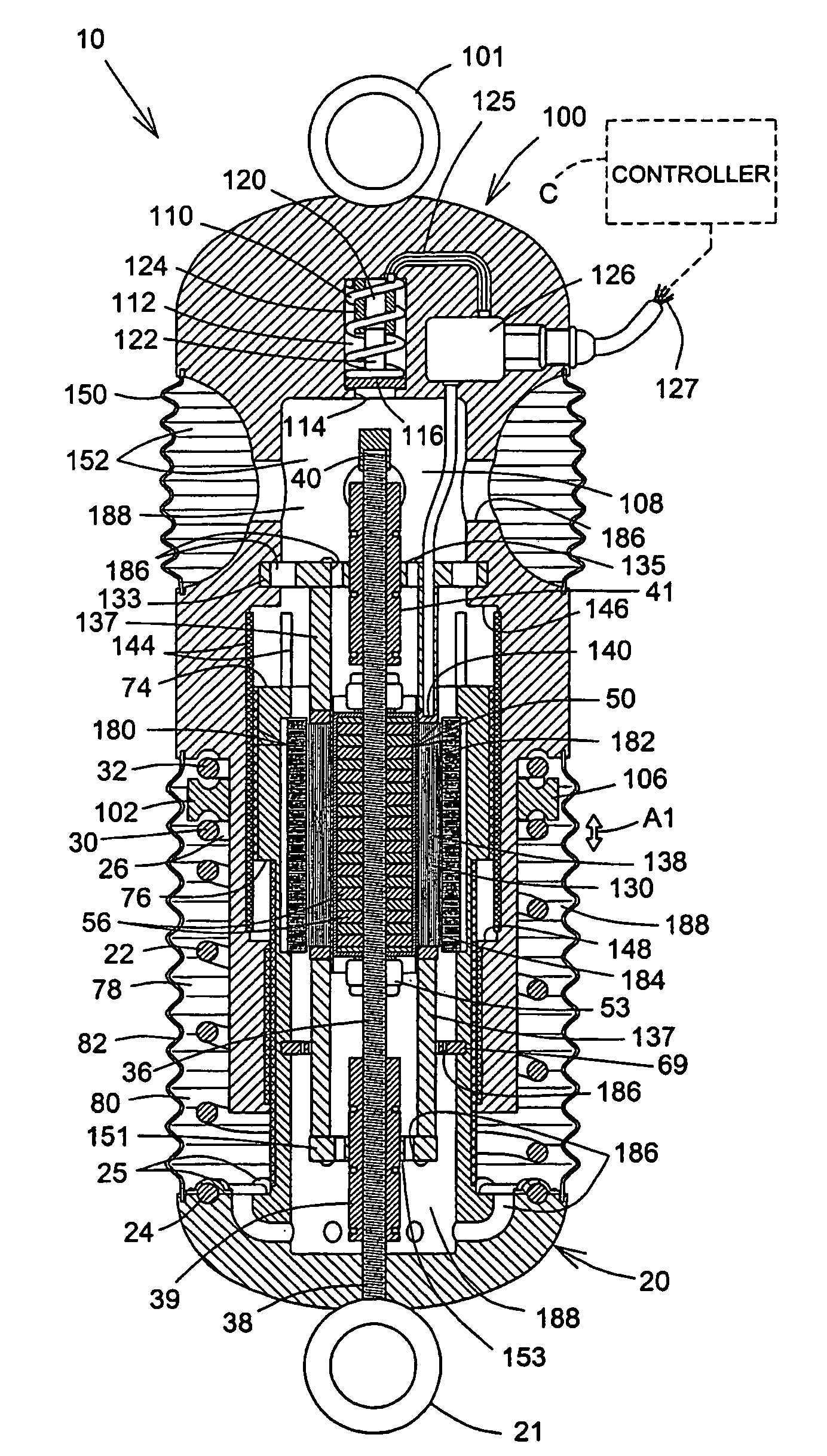
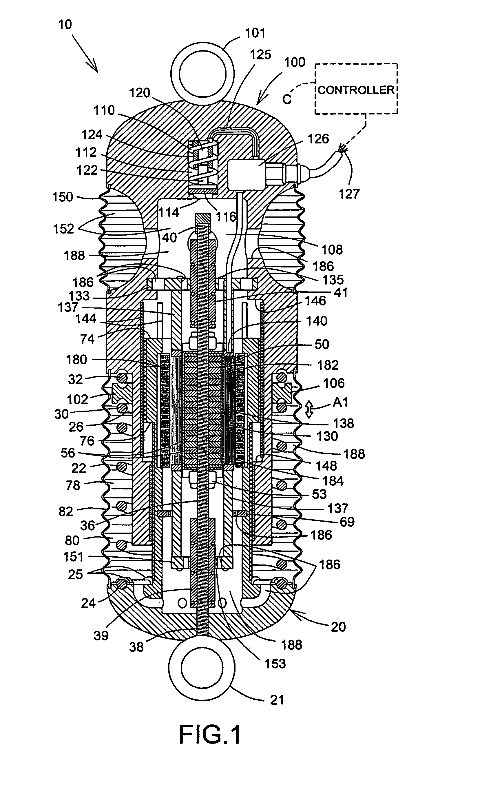
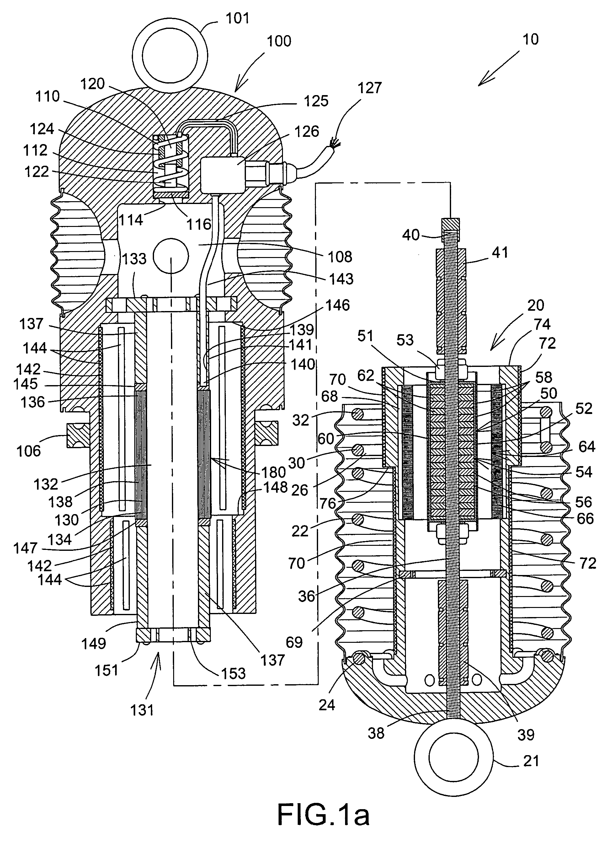
[0069]Referring to FIGS. 1 and 1a, there is shown a linear generator apparatus 10 in accordance with an embodiment of the present invention connectable to an electrical power accumulator, electrical load or the like (not shown). The apparatus 10 includes first and second elongated bodies 20 and 100. The first, and second bodies 20, 100, or magnet housing and coil housing respectively, are generally coaxial relative to one another and generally axially movable relative to one another with a reciprocating movement, as indicated by arrow A1. An annular ring 21 secured on the first body 20 is a means to secure the first body 20 to a part such as a vehicle chassis for example. Similarly, an annular ring 101 secured on the second body 20 is a means to secure the second body 100 to a part such as a vehicle wheel ass...


PUM


Abstract

A linear generator apparatus includes first and second elongate coaxial bodies that are axially movable relative to one another with a reciprocating movement. The first body is axially and freely movable relative to the second body within a predetermined displacement range or free zone. A helical spring connecting to both first and second bodies biases the first body toward the free zone relative to the second body when outside of the free zone. An electrical power generator mounted on both first and second bodies generates power when the first and second bodies axially move relative to one another within the free zone and beyond. The invention also relates to a suspension system for motor vehicle that includes a coil spring and the apparatus in replacement of a conventional shock absorber.

Description

CROSS-REFERENCE TO RELATED APPLICATION[0001]The present application is related to U.S. Provisional Application for Patent Ser. No. 60 / 528,724 filed on Dec. 12, 2003.FIELD OF THE INVENTION[0002]The present invention relates to linear generator apparatuses, and is more particularly concerned with energy collected by a linear generator apparatus for mounting on a circulating vehicle in relation with the corresponding surface onto which the motor vehicle is in motion.BACKGROUND OF THE INVENTION[0003]It is well known in the art to use the energy of vehicles traveling, such as in braking for example. This is becoming more and more a necessity nowadays considering the increasing electrical consumption of today's vehicles for various electronic devices. Moreover, the also increasing demand of electrical or hybrid vehicles requires designers and engineers to come up with ways to have better and innovative ways of recuperating and storing the energy to be used in a limited space. Considering ...

Claims


Application Information

Patent Timeline
Patent Type & Authority Patents(United States)
IPC IPC(8): H02K41/00B60G11/50B60G99/00B60R16/02H02K7/10H02K7/18
CPCB60G13/14B60G17/0157F16F1/13H02K7/1876B60G2200/14B60G2202/312B60G2202/42B60G2300/60
Inventor BEAULIEU, GERALD
Owner BEAULIEU GERALD
Learn More