
Electronic device having touch sensor

a technology of touch sensor and electronic device, which is applied in the direction of coding, pulse technique, instruments, etc., can solve the problems of not preventing from forming any projection or discolored portion on the surface of the electronic device, and achieve the effect of reducing the cost of the electronic devi

Active Publication Date: 2007-07-10
ALPS ALPINE CO LTD
View PDF11 Cites 27 Cited by
  • Summary
  • Abstract
  • Description
  • Claims
  • Application Information

AI Technical Summary

Benefits of technology

[0013]Since the electronic device of the invention can be installed the main body of the touch sensor within the casing forming an appearance of the electronic device, the presence of the touch sensor can be hidden from the outside view. Since no projection or no discolored portion is formed on the surface of the casing of the electronic device, the degree of freedom in the design of the casing surface can be enhanced and the operational ability can be also enhanced. Accordingly, a robot toy, for example, in imitation of an animal can reproduce the original animal itself, and therefore, an animal-shaped robot toy of high reality can be provided. This, however, is not to prevent from forming any projection or discolored portion on the surface of the casing of the electronic device but whether the projection or discolored portion is provided or not depends on the design of the electronic device.
[0015]In the above means, the touch sensor can be simply formed with the small number of components. Accordingly, the cost of the electronic device can be decreased.

Problems solved by technology

This, however, is not to prevent from forming any projection or discolored portion on the surface of the casing of the electronic device but whether the projection or discolored portion is provided or not depends on the design of the electronic device.

Method used


Image

  • Electronic device having touch sensor
  • Electronic device having touch sensor
  • Electronic device having touch sensor

Examples


first embodiment

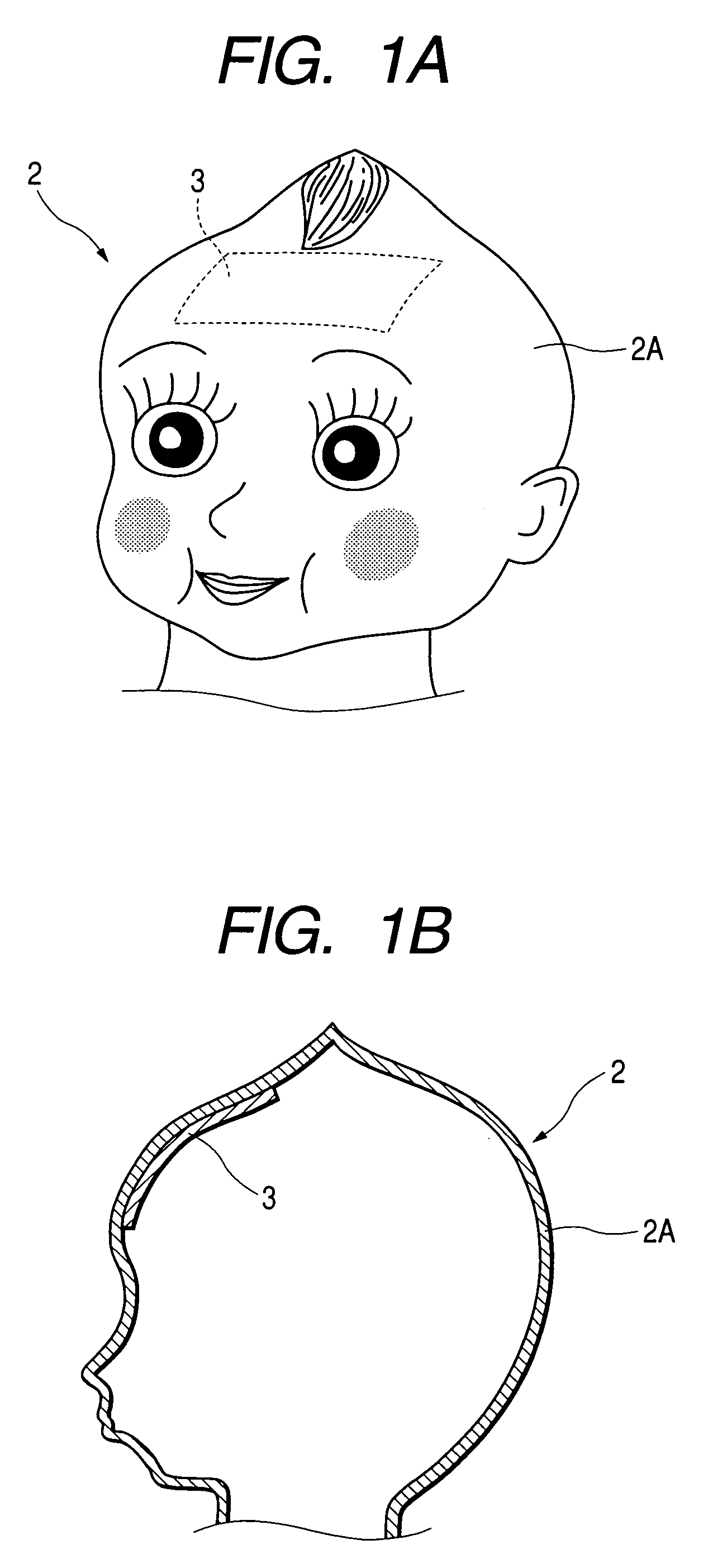
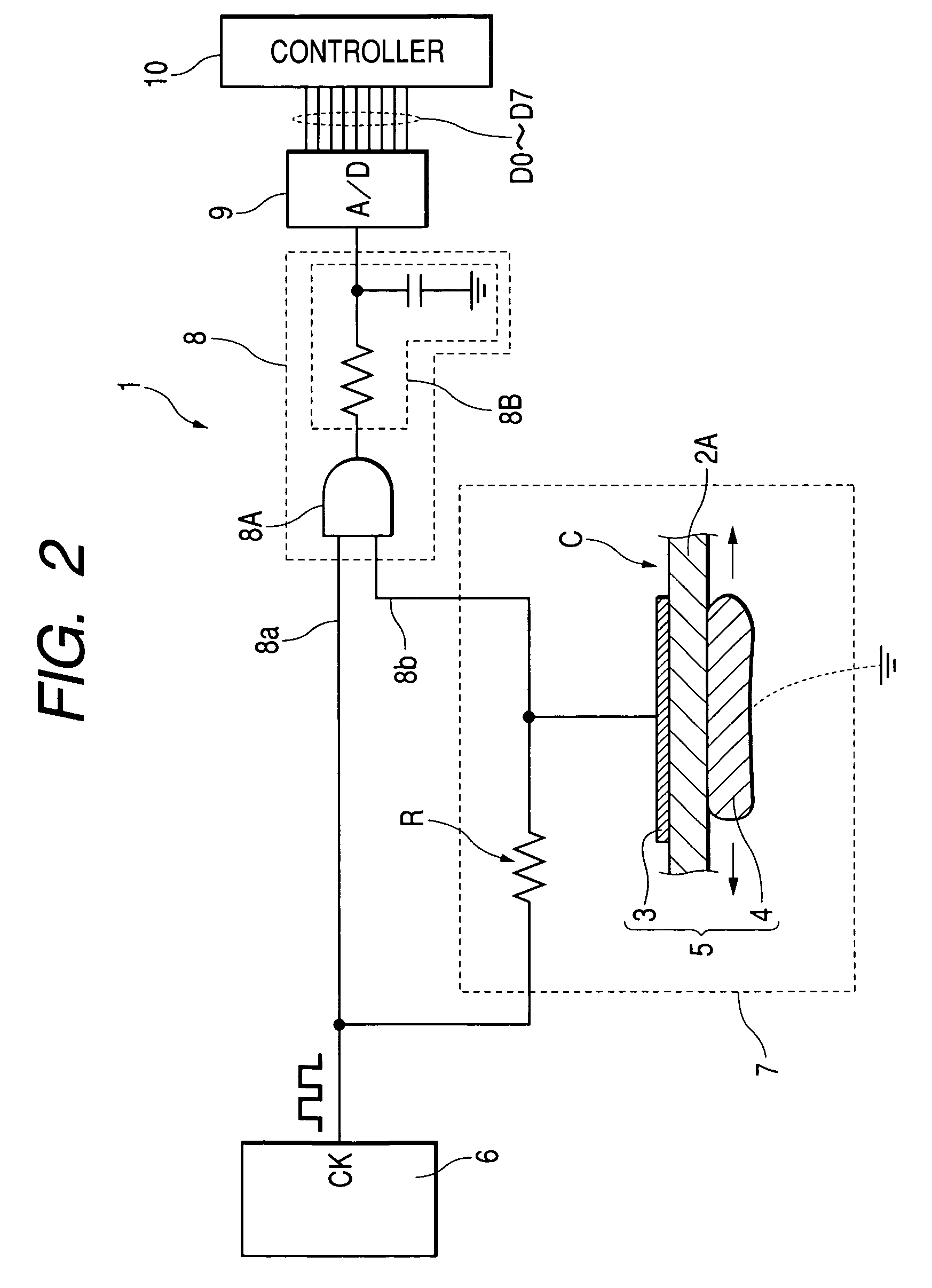
[0027]FIG. 1 shows a head portion of a doll-shaped robot toy as the electronic device having a touch sensor according to the present invention; FIG. 1A is a perspective view of the robot toy and FIG. 1B is a cross sectional view of the robot toy. FIG. 2 is a view of a circuit structure showing the concrete structure of the touch sensor. FIG. 3 shows signals in respective units of the circuit of FIG. 2; FIG. 3A shows a clock signal entered into one input unit of the AND circuit, 3B shows an output signal entered into the other input unit of the AND circuit from the signal delaying means, 3C shows an output signal of the AND circuit, and 3D shows an output signal of the smoothing means. The solid line shows the case where the capacitance C is large, and the dotted line shows the case where the capacitance C is small.

[0028]As shown in FIG. 1A and FIG. 1B, a robot toy 2 that is one example of the electronic device of the invention is provided with a touch sensor 1 in the head portion. T...

second embodiment

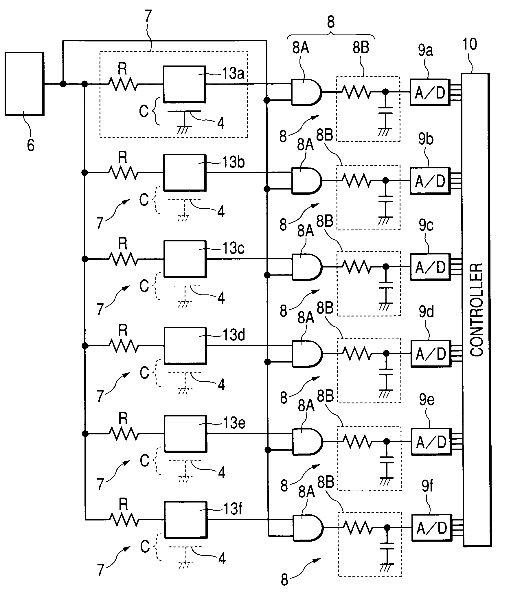
[0049]FIG. 4 is a plane view showing the head portion of a robot toy according to a touch sensor, and FIG. 5 is a circuit constitutional view in the case of providing with a plurality of touch sensors.

[0050]As shown in FIG. 4, in the inner surface of the head portion of the robot toy 2, a plurality of opposed electrodes 13 (each opposed electrode is individually shown as 13a, 13b, 13c, 13d, 13e, and 13f) are aligned on the same circumference with constant pitches. The total sum of the areas of the opposed electrodes 13a, 13b, 13c, 13d, 13e, and 13f is set equal to the area of the opposed electrode 3 of the first embodiment or the more. When the opposed electrode 13 is divided into small portions, the individual areas of the opposed electrodes can be decreased. Therefore, even if the inner surface of the casing 2A is more or less complicated or even if the space on the surface of the electric device is restricted, the respective opposed electrodes 13a to 13f can be arranged there.

[00...


PUM


Abstract

A variable capacitance unit is formed between one portion of a human body and an opposed electrode facing it through a casing of a robot toy (electronic device) when the one portion of the human body such as a hand or a finger approaches the surface of the casing of the robot. Since the capacitance of the variable capacitance unit varies according to the facing area and the facing distance of the one portion of the human body and the opposed electrode, it is possible to detect the one portion of the human body approaching or touching the robot toy by detecting this change. Since the opposed electrode forming the touch sensor can be provided within the casing, the touch sensor cannot be seen directly from the outside of the robot toy.

Description

BACKGROUND OF THE INVENTION[0001]1. Field of the Invention[0002]The present invention relates to an electronic device such as a robot toy, PDA, a cellular phone, and a video camera, and especially to an electronic device having a touch sensor that detects the approach or touch with one of a human body such as a hand and a finger.[0003]2. Description of the Related Art[0004]As the conventional technique of the electronic device having this kind of touch sensor, there exists the invention, for example, described in the patent article 1.[0005]The above patent article 1 discloses a robot toy with a cover which can be pushed down provided on the top surface of the head, and having a touch sensor or a tact switch in the bottom portion of this cover.[0006]In the robot toy described in the patent article 1, a push of the cover sets the tact switch ON. Then, a mood counter counts up and down according to the presence of a pressure operation of the head and the manner of the pressure operatio...

Claims


Application Information

Patent Timeline
IPC IPC(8): H03K17/94A63H11/00B25J19/02G01D5/24H01H36/00H03K17/955H03K17/96
CPCG01D5/24G01D5/2405H03K17/962H01H2231/01H01H2239/006H03K17/9622H03K2217/96072
Inventor SATO, KUNIOENDO, YOSHIHISASOMA, MASAHIRO
Owner ALPS ALPINE CO LTD
Learn More