
Vertical and horizontal adjustable hinge assembly

a vertical and horizontal adjustment technology, applied in the field of hinge technology, can solve the problems of misalignment of gates and fence posts, difficult to achieve horizontal and vertical alignment of two hinged components or hinged component assemblies, and difficult to achieve the task of aligning, so as to facilitate selective and ready adjustment, facilitate installation and adjustment, and facilitate the effect of convenient selection and preparation

Inactive Publication Date: 2007-07-10
BONHAM BRENT
View PDF46 Cites 72 Cited by
  • Summary
  • Abstract
  • Description
  • Claims
  • Application Information

AI Technical Summary

Benefits of technology

The adjustable hinge assembly enables efficient, accurate, and proper alignment of hinged components, reducing the need for multiple installers and minimizing misalignment issues, while maintaining structural integrity and ease of installation.

Problems solved by technology

Successfully aligning two hinged components or hinged component assemblies together, such as a hinged gate and fence post assembly, in both the horizontal and vertical directions, can be very difficult.
The task of aligning is made all the more difficult in the case of assembling hinged components together that are both large and with heavy.
This invariably leads to misalignment of the gates with the fence posts once both sides of the gates are mounted.
Misalignment may be the result of improper initial alignment due to misjudgment in the position of the hinges on the respective counterparts.
Or, misalignment may occur once the gates are allowed to hang under their own weight.
Although the gates and the posts may have been aligned initially, the gates, under their own weight, may cause the hinges to sag.
For instance, significant settling of the fence and / or gate posts may occur, thus contributing to the misalignment.
Or, extended use and environmental conditions may contribute to the misalignment.
In any event, the difficulty in properly aligning the gates to the fence posts using prior known hinges and methods can lead to poor work quality and improper operating relationship between the hinged components.
This is particularly true if initial alignment is off, which can occur as installers are often under significant time constraints.
This often leaves unsightly marks and / or holes in the hinged components that must be masked if possible.
Proper alignment of hinged components is made even more difficult when the hinged components are supported on a sloped elevation.
However, this arrangement for horizontal adjustment is difficult due to the tedious nature of rotating each nut to a new position on the horizontal screw.
Moreover, due to the design configuration of the gate and post brackets, little room is available for turning and tightening the nuts.
Such horizontal adjustment is even more problematic when it is required on multiple hinge assemblies, such as for an upper and lower hinge on each side of a two-panel gate, as is often the case.
However, the vertical adjustment for each hinge assembly disclosed in these references is limited to under half the effective length of the vertical pin coupling the first and second hinges together.
Such limited vertical adjustment does not solve the large vertical adjustments needed for a large and heavy fence and gate assembly and, further, does not solve several inherent operating or functioning issues, such as that of binding the mounting portions of the hinge assembly during operation or actuation of the gate.

Method used


Image

  • Vertical and horizontal adjustable hinge assembly
  • Vertical and horizontal adjustable hinge assembly
  • Vertical and horizontal adjustable hinge assembly

Examples


Embodiment Construction

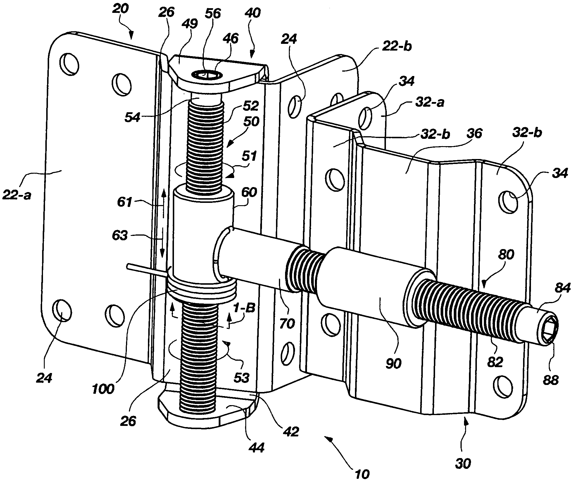
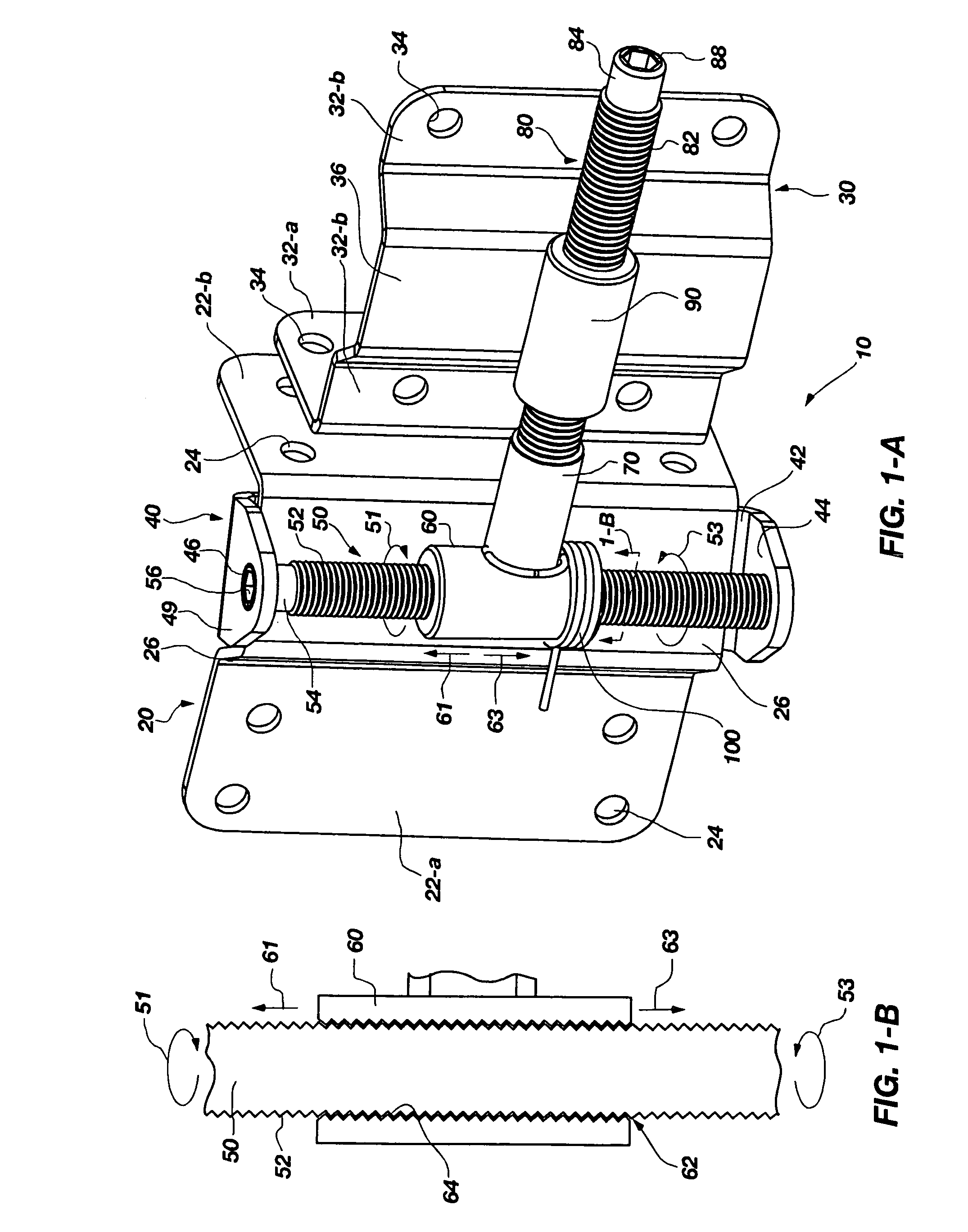
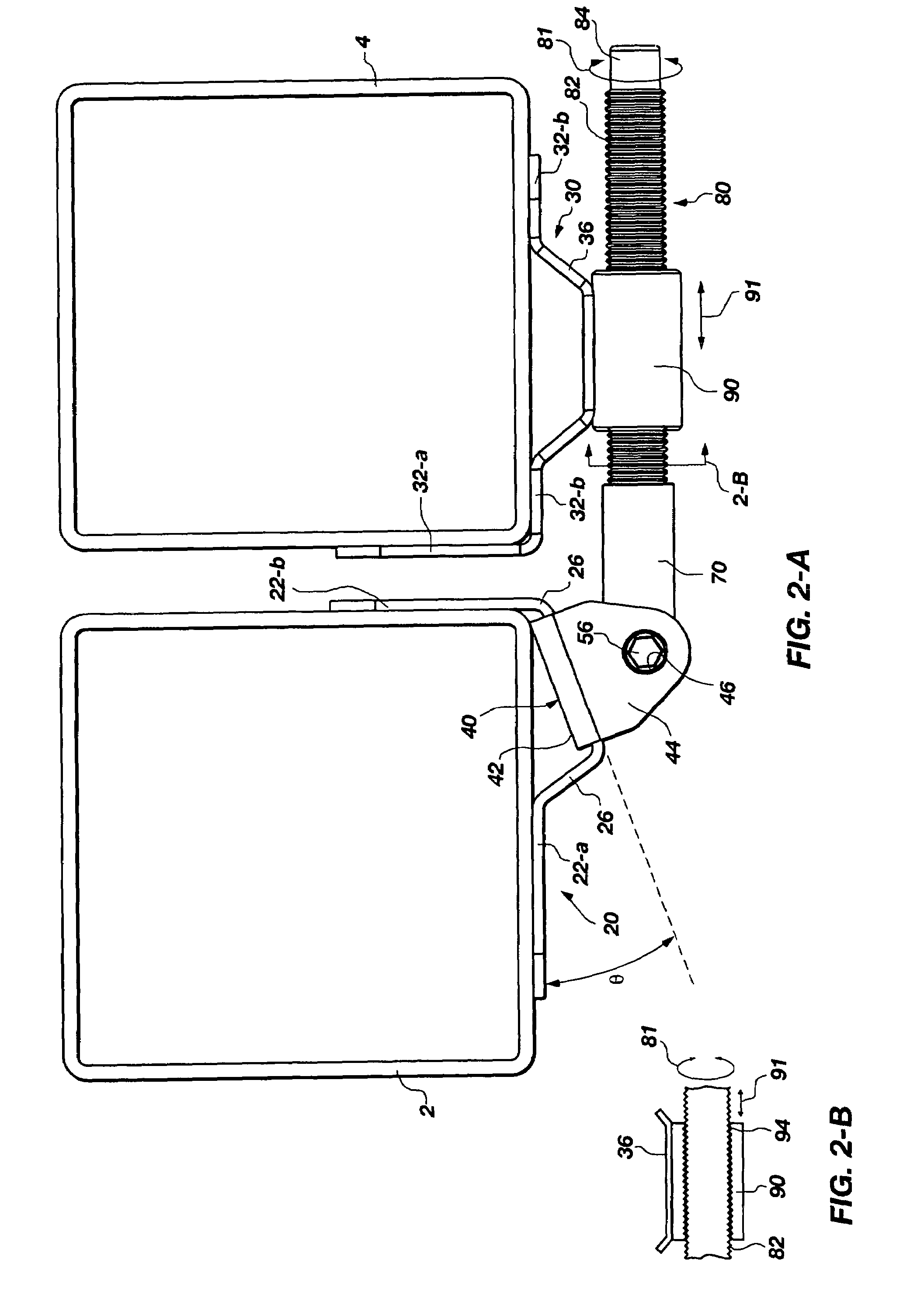
[0089]The following detailed description of exemplary embodiments of the invention makes reference to the accompanying drawings, which form a part hereof and in which are shown, by way of illustration, exemplary embodiments in which the invention may be practiced. While these exemplary embodiments are described in sufficient detail to enable those skilled in the art practice the invention, it should be understood that other embodiments may be realized and that various changes to the invention may be made without departing from the spirit and scope of the present invention. Thus, the following more detailed description of the embodiments of the present invention, as represented in FIGS. 1 through 54, is not intended to limit the scope of the invention, as claimed, but is presented for purposes of illustration only and not limitation to describe the features and characteristics of the present invention, to set forth the best mode of operation of the invention, and to sufficiently enab...


PUM


Abstract

A method and apparatus providing an adjustable hinge configured for a fence post and gate assembly of a fence. The adjustable hinge includes a first bracket operable to be secured to a first portion of the fence and a second bracket operable to be secured to a second portion of the fence. The adjustable hinge also includes a vertical adjustment component, a horizontal adjustment component, a hinge barrel and a collar. The vertical adjustment component is operably coupled to the first bracket and the horizontal adjustment component is operably coupled to the second bracket. The hinge barrel is operable to be rotatably coupled to the vertical adjustment component and the horizontal adjustment component. The collar is operable to be rotatably coupled to the horizontal adjustment component and is operably coupled to the second bracket. With this arrangement, the hinge barrel is operable to be moveable along the vertical adjustment component to vertically adjust the second bracket with respect to the first bracket. Furthermore, the collar is operable to be moveable along the horizontal adjustment component to horizontally adjust the second bracket with respect to the first bracket.

Description

RELATED APPLICATIONS[0001]This application claims priority to U.S. Provisional Application Ser. No. 60 / 513,668, filed Oct. 23, 2003, and entitled, “Vertical / Horizontal Adjustable Hinge,” which is incorporated by reference herein in its entirety.FIELD OF THE INVENTION[0002]The present invention relates generally to hinge technology. More particularly, the present invention relates to a vertically and horizontally adjustable hinge and various means for carrying out vertical and horizontal adjustment of the hinge for proper and accurate alignment of the hinged components.BACKGROUND OF THE INVENTION AND RELATED ART[0003]Successfully aligning two hinged components or hinged component assemblies together, such as a hinged gate and fence post assembly, in both the horizontal and vertical directions, can be very difficult. The task of aligning is made all the more difficult in the case of assembling hinged components together that are both large and with heavy. For example, aligning double ...

Claims


Application Information

Patent Timeline
Patent Type & Authority Patents(United States)
IPC IPC(8): E05D7/04E05DE05D5/06E05D7/00E05D13/00E05F1/12
CPCE05D5/06E05D7/0027E05D7/0415E05D7/0423E05F1/1215E05D3/10E05D2007/0036Y10T16/534E05Y2600/20E05Y2900/40Y10T16/5595Y10T16/53225E05Y2201/702
Inventor BONHAM, BRENT
Owner BONHAM BRENT
Learn More