
Machine to automate dispensing of pills

a machine and pill technology, applied in the field of medicine, can solve the problems of not providing the proper amount to the consumer, difficult to remember which pill to take, when to take it, and even whether

Active Publication Date: 2007-06-05
QEM INC
View PDF27 Cites 88 Cited by
  • Summary
  • Abstract
  • Description
  • Claims
  • Application Information

AI Technical Summary

Benefits of technology

[0016]In one embodiment, a pill dispensing device is disclosed including at least one cassette for storing a supply of pills with a control for releasing a quantity of the pills from a selected cassette at a target location. A movable platen holds either a bl

Problems solved by technology

Although Pharmacists are very careful to dispense the correct quantity of the correct medicine, ever too often, the wrong quantity is dispensed, or worse yet, the wrong medicine is dispensed.
Again, the transfer of pills into the container creates another opportunity for one or more pills to be lost, thereby not providing the proper amount to the consumer.
With some consumers, it may be difficult to remember which pill to take, when to take it, and even whether they have already taken the pill.
Furthermore, for prescriptions in which the dosage varies by day, extra attention to detail is required because each blister may have different quantities of pills or pills of a different strength or a combination of such, again feeding into the probability of error.
This device is limited to dispensing a fixed quantity of a single type of pills into bottles.
This device is limited to dispensing a single type of pill into a single type of blister pack.
Although not limited to one medication as the previous patents, this device is limited to dispensing only into blister packs.
Unfortunately, the prior art does not have one dispensing apparatus that dispenses to either a vial or a punch card, requiring the pharmacy to purchase two independent dispensing machines, one for vials and the other for punch cards.
Besides imposing a cost burden upon the pharmacy for two independent dispensers, the duplication of machines requires extra space, consumes more power and, where the same pills are stored in cassettes of both machines, dual supplies of those pills is required, increasing inventory.
These issues often lead a pharmacy to select one packaging type over the other.
That choice is usually the vial type, almost limiting the consumer to only receiving medication in vials; preventing the consumer from reaping the benefits of blister packs.

Method used


Image

  • Machine to automate dispensing of pills
  • Machine to automate dispensing of pills
  • Machine to automate dispensing of pills

Examples


first embodiment

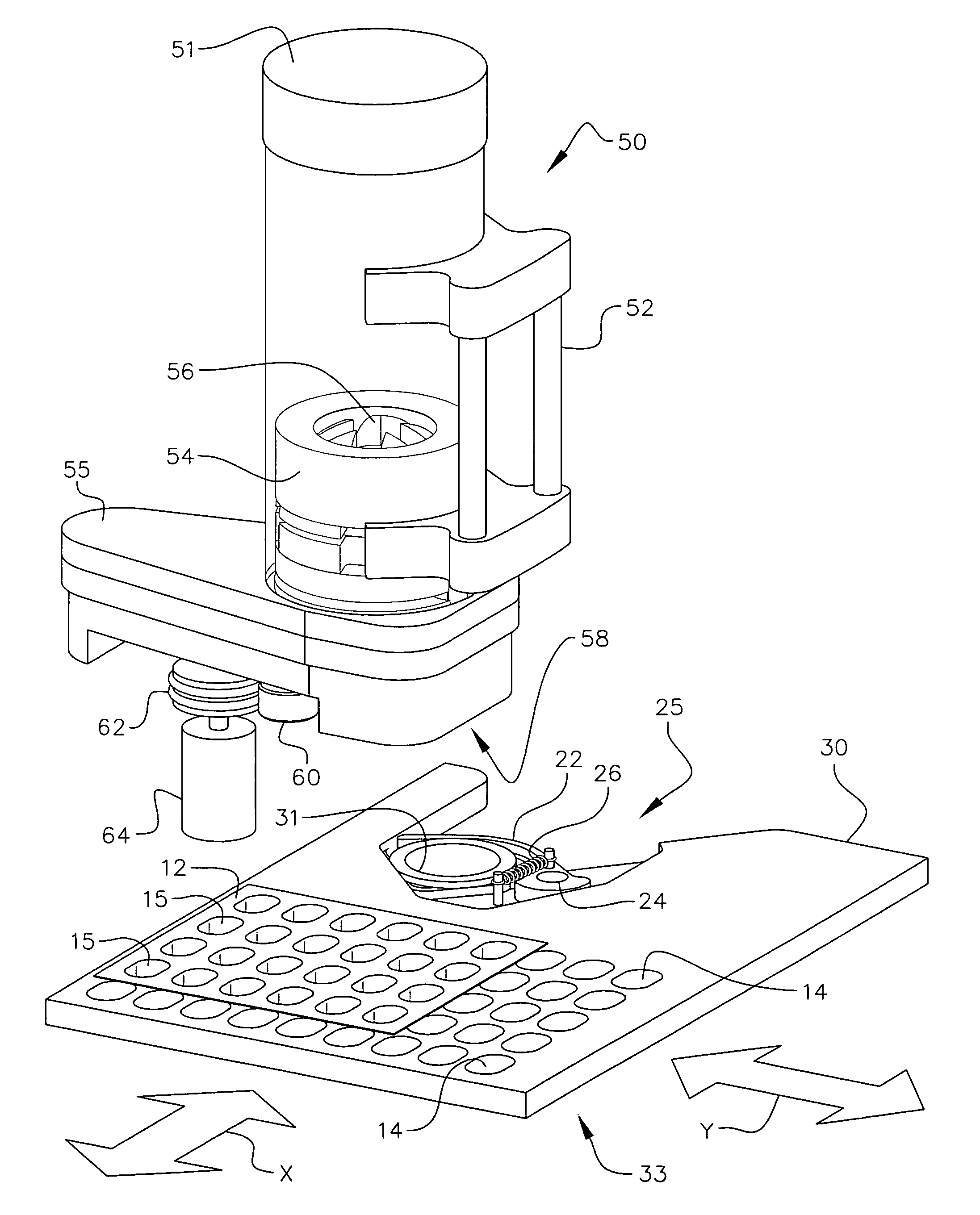
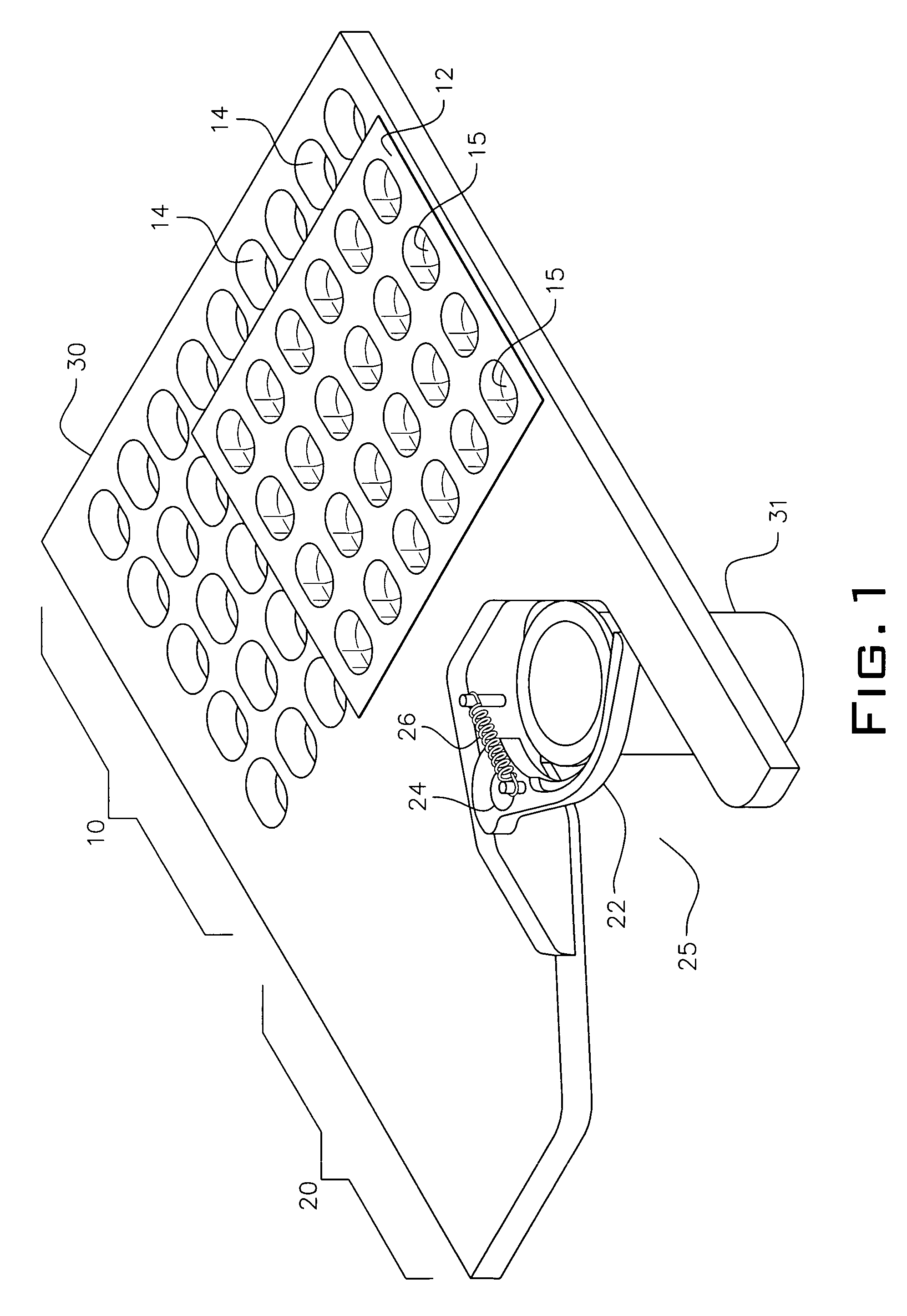
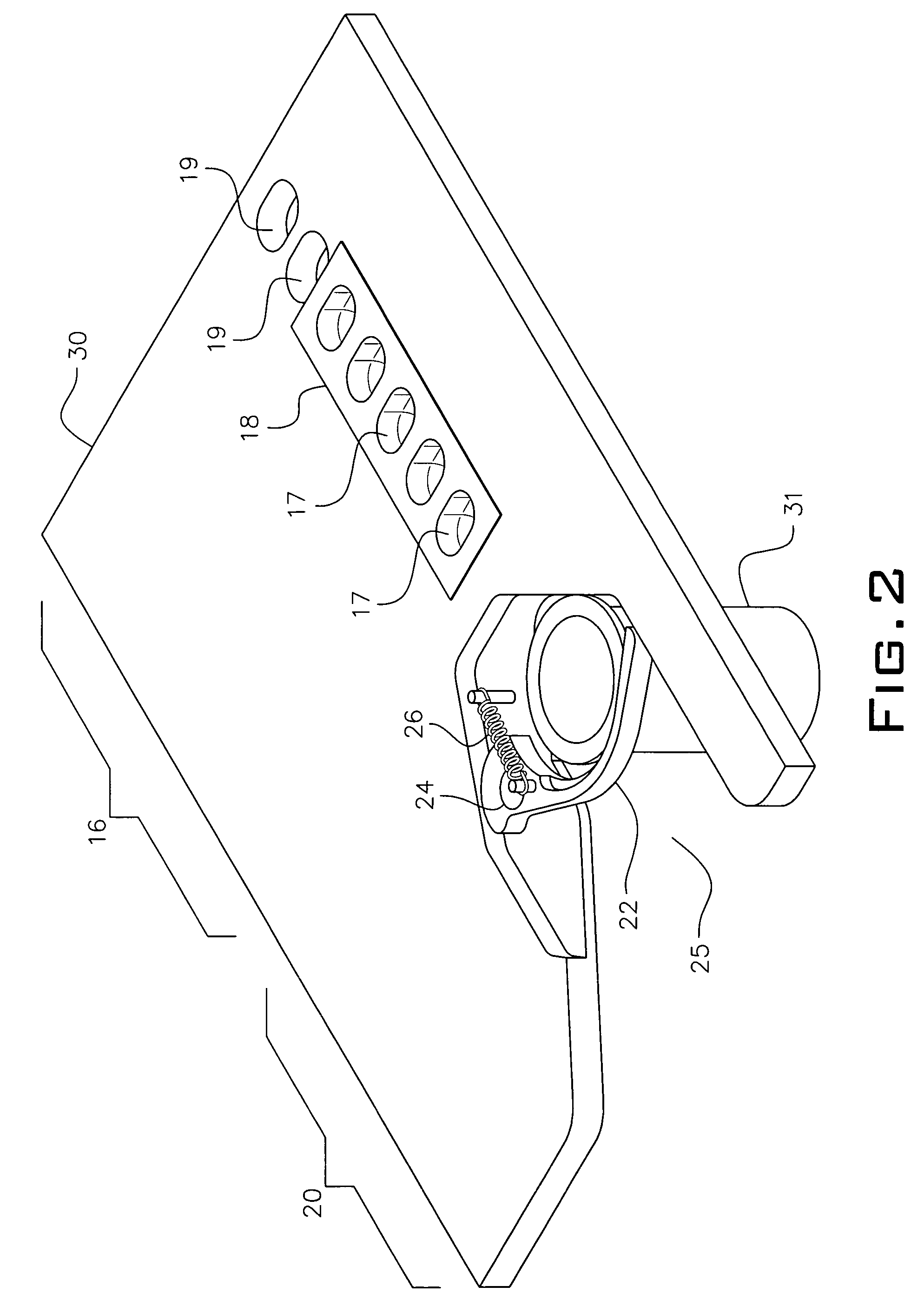
[0031]Referring to FIG. 1, a top plan view of a platen of the present invention is shown. The platen frame 30 is made from a substantially flat material. In the preferred embodiment, the platen frame 30 is made from a metal such as steel but in other embodiments, the platen frame 30 is made from a hard plastic. The platen frame 30 has an area for accepting a blister pack 10 and an area for accepting a vial 20. The area for accepting a blister pack 10 has a plurality of holes or indentations 14 in which the individual blisters 15 of a blister pack 12 rest, thereby holding the blister pack 12 in place. In some embodiments, holes 14 are bored through the platen frame 30 while in other embodiments, indentations 14 are carved or formed in the platen frame 30. In one embodiment, the number of holes or indentations 14 matches the number of blisters 15 in the blister pack 12 while in other embodiments, the number of holes or indentations 14 exceed the number of blisters 15 in the blister pa...

third embodiment

[0038]Referring to FIG. 4, a perspective view of the present invention with a movable cassette dispensing unit is shown. The platen 37 is a platen as described in the previous description except that in this embodiment, the platen 37 is stationary. Instead of moving the platen 37, the drive mechanism moves the cassette and in some embodiments, moves the entire cassette carousel, thereby positioning the dispensing cassette 50 over the target blister 15 or vial 31. In some embodiments, the control mechanism is one or two servo motors, moving the cassette 50 in either an X direction or an X and Y direction. If the stationary platen 37 is designed to hold a blister pack 12 with a single row of blisters 15 (see FIG. 2), the control mechanism need only move in an X direction while if the stationary platen 37 is designed to hold a blister pack 12 with multiple rows, each having multiple blisters 15, then the control mechanism needs to move the cassette in an X and Y direction to index to e...

fourth embodiment

[0041]Referring to FIG. 5, a perspective view of the present invention with a linear dispensing unit is shown. In this embodiment, the movable platen 33 is driven in an X direction by a first motor 120 coupled to a threaded shaft 122. The threaded shaft 122 is long enough to allow the movable platen 33 to travel under a plurality of cassettes 50. In one embodiment, the threaded shaft 122 is held at an end distal to the first motor 120 by a support 130. The first motor 120 and the support 130 freely travel in they direction by way of rails 121 / 131. The rails are held in place by anchors 123 / 133. The threaded shaft 122 interfaces to the platen 33 at a linkage 126 that pulls or pushes the platen 33 along the length of the threaded shaft 122; thereby creating what is known as a worm gear. The cassettes 50 are similar to the previously described cassette, but each cassette in this embodiment has a separate drive motor 64 to cause the dispensing of pills. The first motor 120 is capable of...


PUM


Abstract

A device having a plurality of cassettes, each filed with a supply of pills and positionable over a target location. The device has a platen beneath the target location with receptacles configured to hold both vials and blister packs. The platen or the cassette is movable so that any blister of the blister pack or the vial can be positioned under the target location to receive a quantity of pills from a cassette.

Description

BACKGROUND OF THE INVENTION[0001]This application is related to U.S. application titled, “CASSETTE FOR DISPENSING PILLS,” which was filed on even date herewith; Ser. No. 11 / 317,538 and inventors Norman D. Knoth and Jeffrey A. Johnsey.[0002]1. Field of the Invention[0003]The present invention relates to the field of dispensing medicine and more particularly to an apparatus that automatically fills vials and blister packs with medicine in the form of pills, capsules, gel-caps and the like.[0004]2. Description of the Related Art[0005]The dispensing of medicine in the form of pills, capsules, gel-caps, and the like is performed in many ways and in many locations including pharmacies, packaging plants and hospitals. Pharmacies or drug stores employ Pharmacists to fill prescriptions with the prescribed amount of a prescribed medicine or dose. The Pharmacist fills the prescription from a bulk package of medicine into a delivery package sized for the consumer. Although Pharmacists are very ...

Claims


Application Information

Patent Timeline
IPC IPC(8): B65B1/04
CPCB65B5/103
Inventor KNOTH, NORMAN D.
Owner QEM INC
Learn More