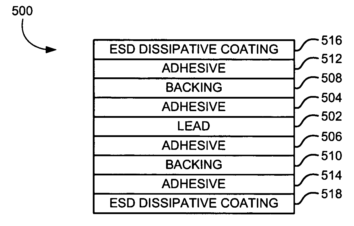
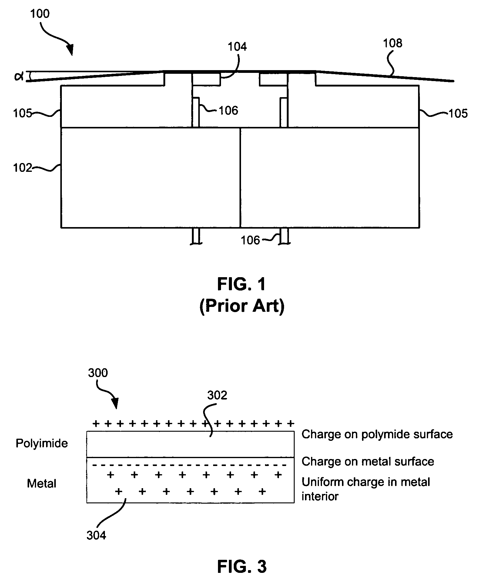
The smaller the dimensions, the more sensitive the thin sheet resistors become to damage from spurious current or voltage spike.
A major problem that is encountered during manufacturing, handling and use of MR sheet resistors as magnetic recording transducers is the buildup of electrostatic charges on the various elements of a head or other objects which come into contact with the sensors, particularly sensors of the thin film type, and the accompanying spurious discharge of the static electricity thus generated.
These static charges may be discharged through the head causing excessive heating of the sensitive sensors which result in physical or magnetic damage to the sensors.
As described above, when a head is exposed to voltage or current inputs which are larger than that intended under normal operating conditions, the sensor and other parts of the head may be damaged.
This sensitivity to electrical damage is particularly severe for MR read sensors because of their relatively small physical size.
Discharge currents of tens of milliamps through such a small resistor can cause severe damage or complete destruction of the MR sensor.
The nature of the damage which may be experienced by an MR sensor varies significantly, including complete destruction of the sensor via melting and evaporation, oxidation of materials at the air bearing surface (ABS), generation of shorts via electrical breakdown, and milder forms of magnetic or physical damage in which the head performance may be degraded.
The large number of MR sensors in a tape drive and the requirement that all are functional, makes ESD loss due to a single element very expensive as the entire head must then be scrapped.
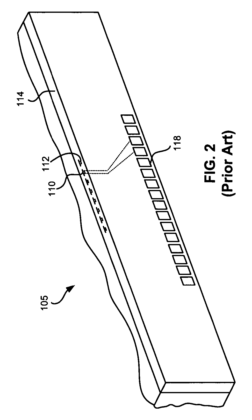
Polyimides are very susceptible to localized charge buildup through tribocharging mechanisms, and the time for the charge to dissipate is very long.
However, if the metal touches a ground, the charge can flow through the delicate MR sensor and cause ESD or EOS damage.
The problem is compounded by the fact that the time for the charge to dissipate into the air is very long. FIG. 4 is a chart showing voltage discharge vs. time for KAPTON / PYRALUX LF7001 (DuPont).
A conductive cable could be used to spread the charge out, but even traditionally ESD dissipative conductives can interfere with the performance of the MR sensor by coupling one sensor to another, or a reader to a writer.
A metal coating on the surface of the cable might also spread the charge out, but could result in excessive electromagnetic interference (EMI) radiation.
Both of these approaches have significant disadvantages.
The problem with this technique is that the head is no longer functional while the short is applied.
Once the short is removed, for testing or use, the sensors are no longer protected.
Furthermore, with a removable short, the action of removing the short could also cause tribocharging of the cable which could potentially damage the sensors.
Potential problems which the diode approach are: 1) drainage of current under normal operation degrading the sensor performance, 2) excessive weight of the diode package affecting mechanical motion of the tape head, 3) excessive cost of adding a multiplicity of diodes, 4) physically being able to fit a multiplicity of diodes onto a cable, and 5) space constraints within a small tape drive.
This has not been implemented in tape drives due to cost issues.
Particularly, since modern tape heads have multiple read elements, it can be expensive to add packages containing individual diodes or pairs of diodes for each element, particularly when the head and cable are scrapped during the testing phase.
While mounting diodes on a single slider may be cost effective, the sheer number of diodes required for a modern tape head can add significant cost to the head.
While diode protection used for disk drives uses a pair of crossed diodes, the voltages applied in to the MR elements in tape heads (e.g., >0.6 V) would cause a single diode to shunt too much current, resulting in degraded performance.
Furthermore, the added weight of many diodes or chips on the cable will affect the dynamics of the head actuation, potentially degrading its track following performance.
Another constraint is the physical space within an extant tape drive requires extremely small components.
Furthermore, the discharge time is very short (e.g., ˜0.1 to 10 ns) when a charged lead comes in contact with a metal object such as a test device or a drive.
Diodes may not be able to respond during this time frame.