
Collapsible vehicle ramp

a vehicle ramp and collapsible technology, applied in the field of vehicle accessories, can solve the problems of bulky devices and occupying a significant amount of storage spa

Inactive Publication Date: 2007-05-29
JI JUN
View PDF7 Cites 24 Cited by
  • Summary
  • Abstract
  • Description
  • Claims
  • Application Information

AI Technical Summary

Benefits of technology

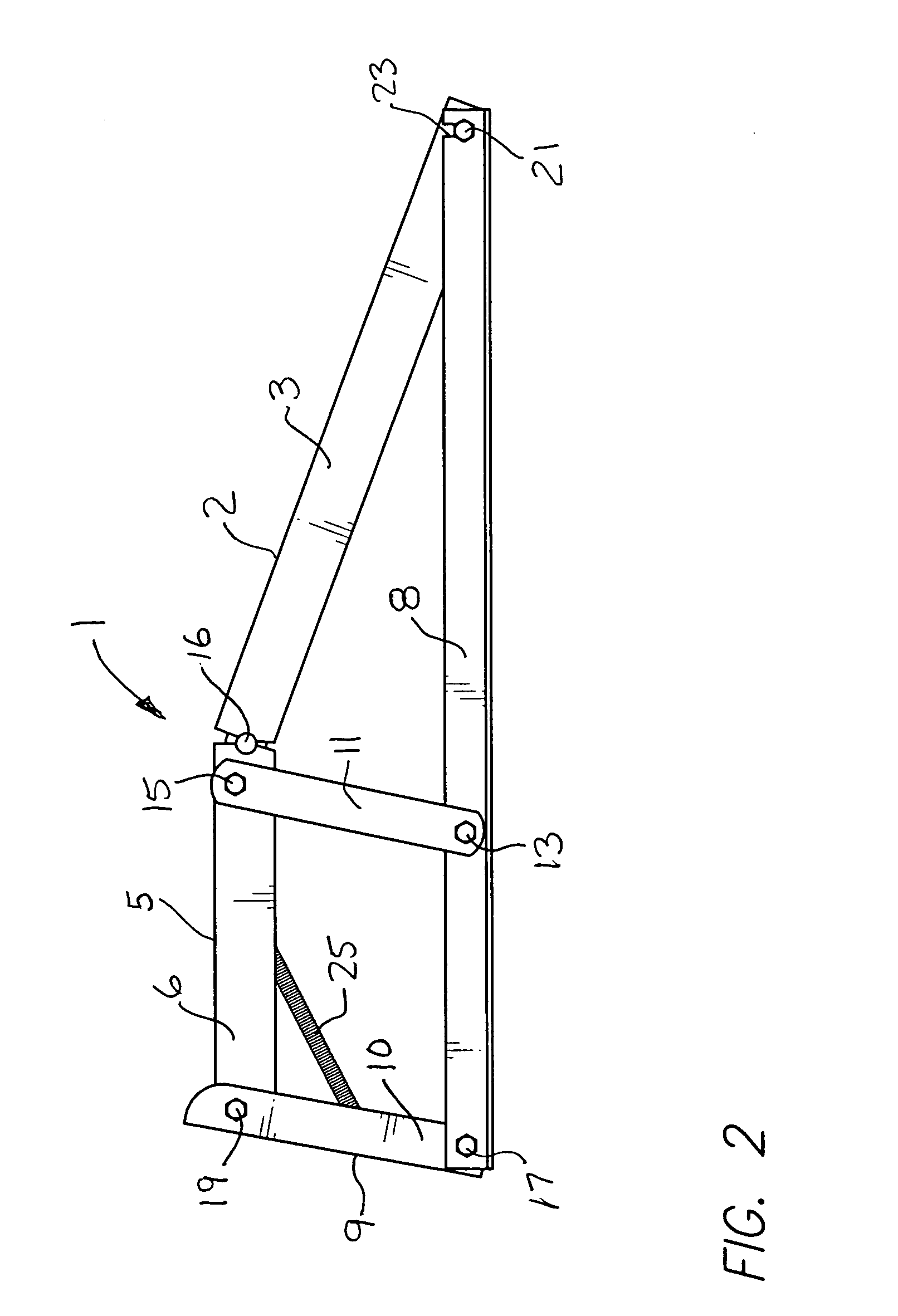
[0010]The present invention provides a vehicle ramp comprising a pair of plate members, pivotally connected together along respective edges thereof. A frame arrangement is articulately connected to the plate members, whereby the plate members can be selectively pivoted with respect to one another to either form a functional raised in-use vehicle ramp configuration, or form a storable, collapsed, low profile configuration in which the two plate members lie in substantially a common plane.
[0011]In a preferred embodiment, there is provided a vehicle ramp comprising a first plate member having a front end and a rear end, and a second plate member having a front end and a rear end. The rear end of the second plate member is pivotally connected to the front end of the first plate member. A frame arrangement, comprised of a plurality of interconnected articulated support members is provided, coupled to the first and second plate members, to permit collapsing the entire assembly from a raised in-use position.

Problems solved by technology

As a result, even in the folded condition, the device is bulky and occupies a significant amount of storage space in a garage, or in the trunk of a vehicle.

Method used


Image

  • Collapsible vehicle ramp
  • Collapsible vehicle ramp
  • Collapsible vehicle ramp

Examples


Embodiment Construction

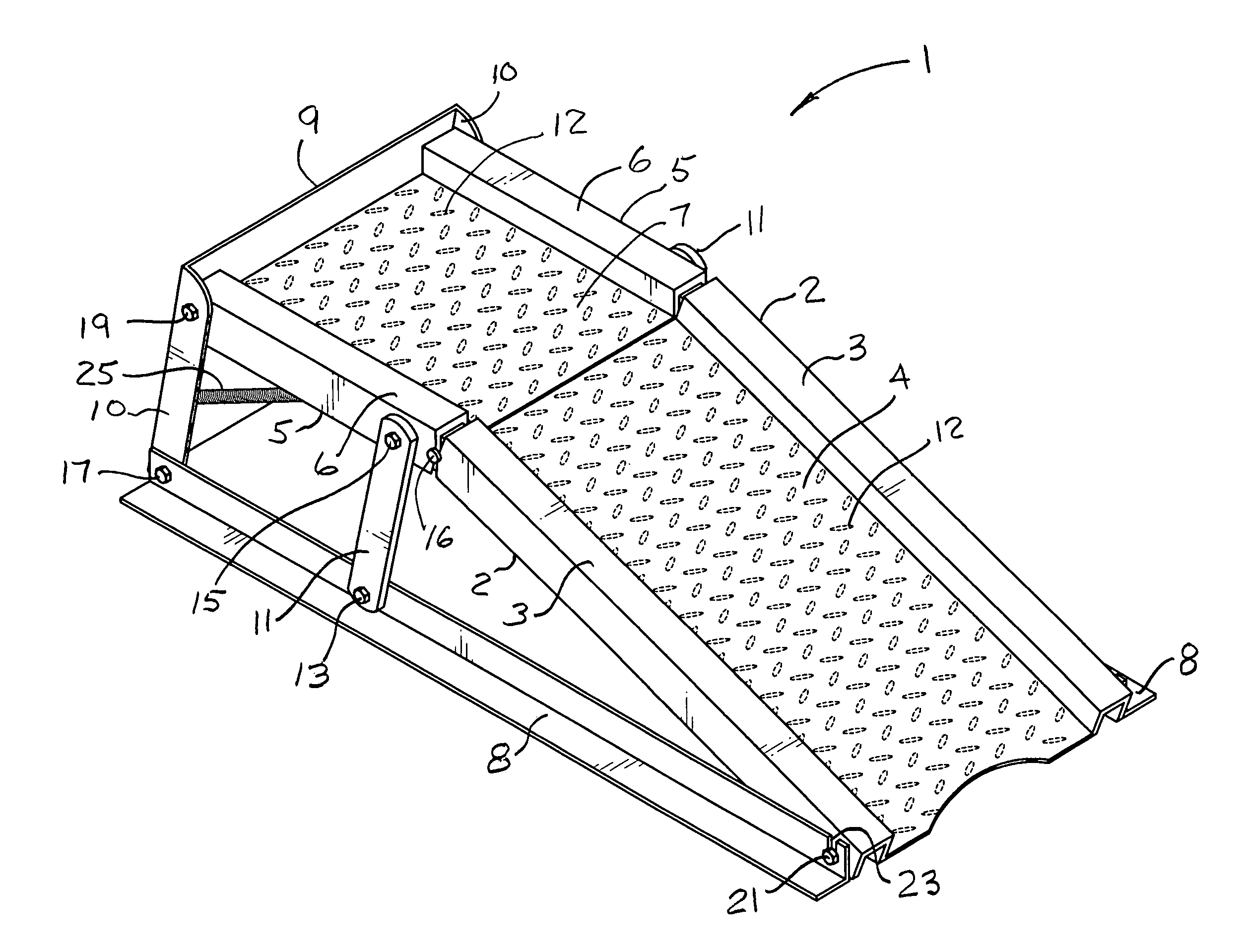
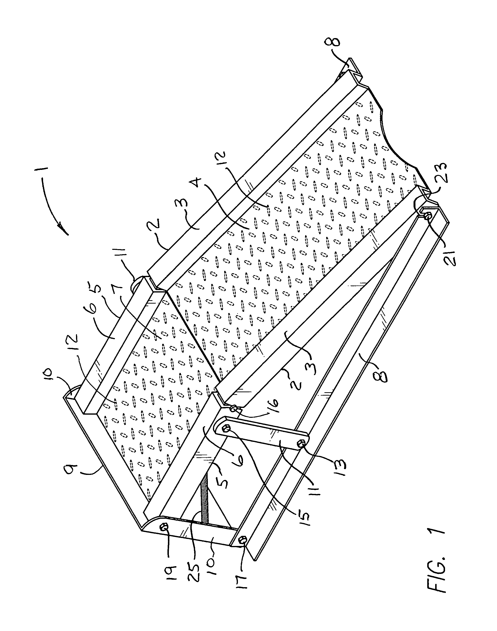
[0021]In FIG. 1, the collapsible vehicle ramp 1 is shown, in perspective representation, in its raised, or in-use configuration.

[0022]A riser plate member 2, hereinafter referred to as riser 2, extends from a reference surface, assumed to be the ground or floor in most cases, to an elevated level, leading to elevated wheel platform plate member 5, hereinafter referred to as platform 5.

[0023]Riser 2 comprises a flat friction plate portion 4 extending between a pair of parallel, U-shaped, raised, riser side channels 3.

[0024]Platform 5 also comprises a flat friction plate portion 7 extending between a pair of U-shaped platform side channels 6.

[0025]It will be understood that the raised diamond grip elements 12, on the two flat friction plate portions 4 and 7, are exemplary only of a frictional surface texture, are not necessarily shown to scale, and may not be depicted in the drawing as they would appear on the actual device.

[0026]In a preferred embodiment, the plate portion 4 and side...


PUM


Abstract

An improvement in a vehicle ramp facilitates easy storage and quick and simple conversion from a stored, collapsed state to an open, in-use state. The vehicle ramp comprises a pair of plate members pivotally coupled together along one side of each respective plate member which, being supported by a frame arrangement articulately connected to the plate members, permits the plate members to be selectively pivoted with respect to one another to either form a functional raised vehicle ramp configuration, or form a storable, collapsed, low profile configuration in which the two plate members lie in substantially a common plane, along with the articulated frame arrangement.

Description

REFERENCE TO DISCLOSURE DOCUMENT CERTIFICATE[0001]Reference is made to U.S. Disclosure Document Certificate No. 587734, recorded Oct. 5, 2005, entitled “Foldable Car Ramp”. The entire contents of such disclosure document is incorporated herein by reference.BACKGROUND OF THE INVENTION[0002]1. Field of the Invention[0003]This invention is related to the field of vehicle accessories, and more particularly to a device for supporting the wheels of a vehicle in a raised position, primarily to permit inspection, repair, and / or maintenance of the underside of the vehicle.[0004]2. Brief Description of the Prior Art[0005]Prior art vehicle ramps are generally in the nature of a fixed structure of steel plates and connecting steel braces.[0006]An example of such a prior art vehicle ramp is a structure that comprises a sloping metal plate welded to a raised horizontal plate, with a steel frame welded, or otherwise secured, to the rear of the raised horizontal plate, and to the front sides of the...

Claims


Application Information

Patent Timeline
Patent Type & Authority Patents(United States)
IPC IPC(8): E02C3/00
CPCB66F7/243
Inventor JI, JUN
Owner JI JUN
Learn More