
Magnetic array position sensor

a position sensor and magnetic array technology, applied in the field of position sensors, can solve the problems of differential sensor, the simplest, but also the least accurate, and the inability to maintain the same high accuracy i

Inactive Publication Date: 2007-05-22
DELPHI TECH INC
View PDF28 Cites 19 Cited by
  • Summary
  • Abstract
  • Description
  • Claims
  • Application Information

AI Technical Summary

Benefits of technology

[0007]Many variations in the embodiments of present invention are contemplated as described herein in more detail. Other applications of the present invention will become apparent to those skilled in the art when the following description of the best mode contemplated for practicing the invention is read in conjunction with the accompanying drawings.

Problems solved by technology

Sensors with a single sensing element are the simplest, but also the least accurate.
The differential sensor, however, cannot maintain the same high accuracy if it is used as a linear sensor, providing a continuous analog output signal proportional to displacement.

Method used


Image

  • Magnetic array position sensor
  • Magnetic array position sensor
  • Magnetic array position sensor

Examples


Embodiment Construction

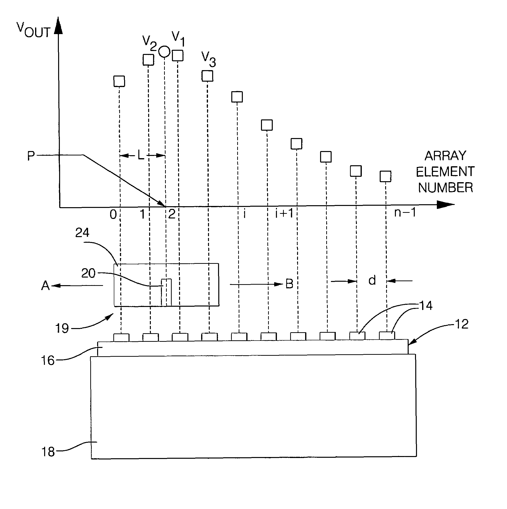
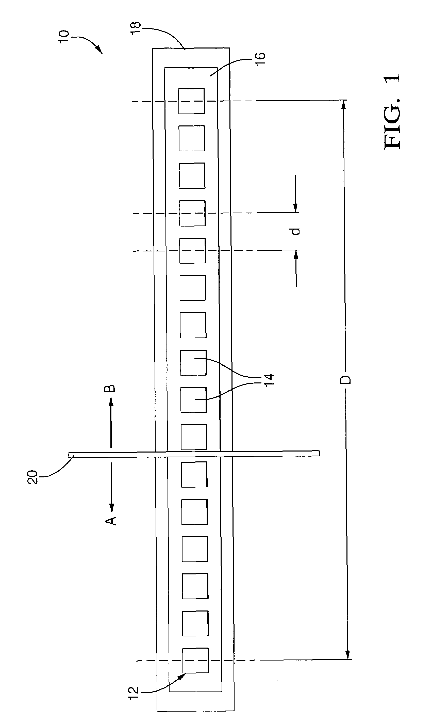
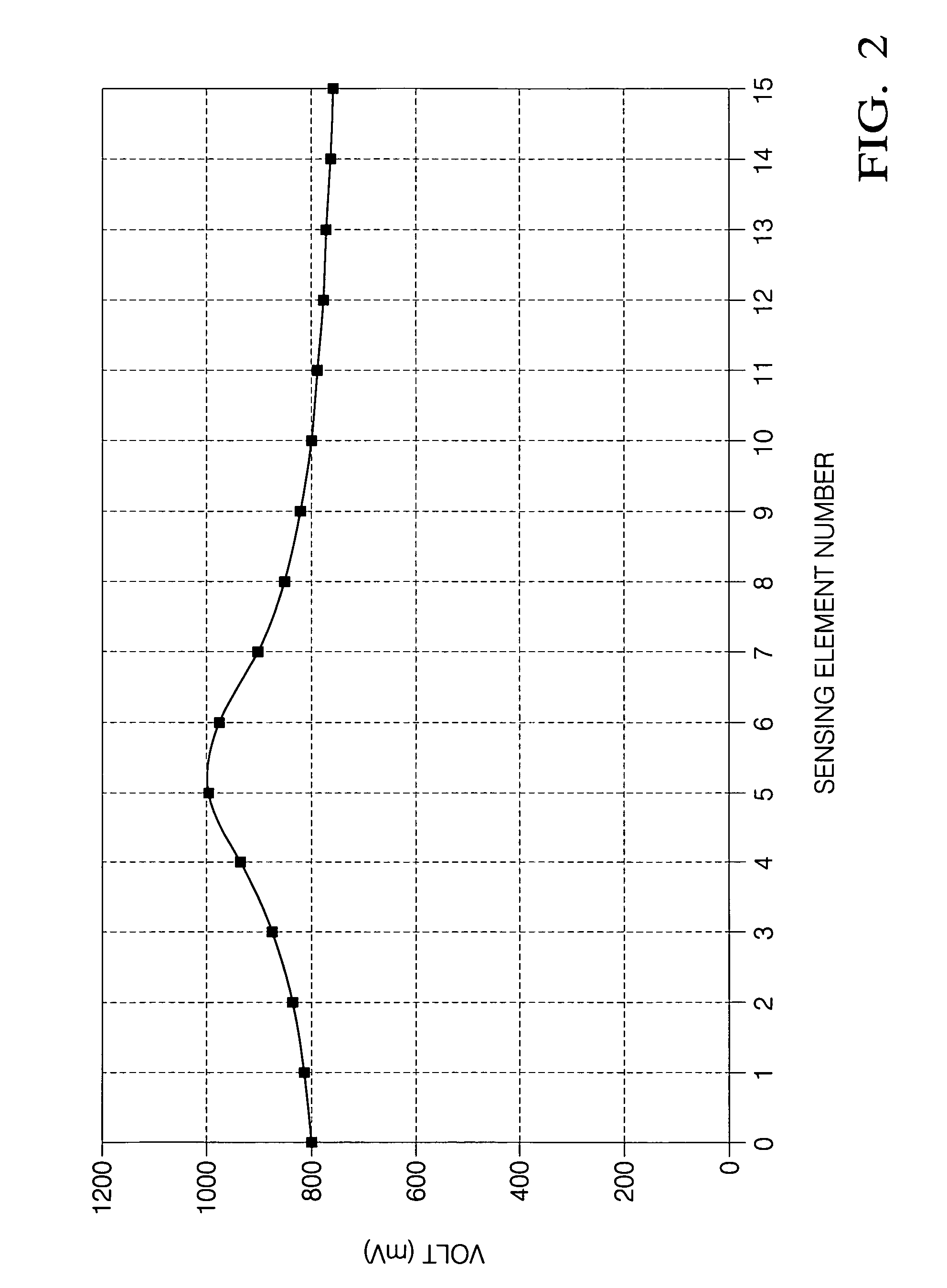
[0023]The use of a magnetic array position sensor as a continuous analog sensor to measure either angular or linear position are shown in the drawing with reference to FIGS. 1-12. The basic principles are illustrated starting with FIGS. 1-5. FIG. 1 shows an array sensor 10 that can be used in the present invention. The sensor 10 includes a linear array 12 mounted on a bias magnet 18. Alternatively, an electromagnet can be used in place of the bias magnet 18. The array 12 is linear, i.e., it comprises a plurality of roughly identical and equidistantly-spaced galvanomagnetic sensing elements 14 on a single die 16. Of course, more than one die 16 can also be used to form the linear array 12. The sensing elements 14 of the linear array 12 can be Hall elements or magnetoresistive elements, by example. Details of the construction of one linear array 12 that can be used in the present invention are disclosed in U.S. Pat. No. 6,201,466, the entire contents of which is incorporated herein by...


PUM


Abstract

A sensor apparatus and method that can measure either a linear position or an angular position of a device. A linear array of galvanomagnetic sensing elements is fixedly mountable adjacent the device. A target is connectable to the device such that the target moves adjacent a surface of the linear array in response to movement of the device and is shaped so that a magnetic flux density curve resulting from excitation of the sensing elements includes a peak and / or a valley. A first circuit excites each of the sensing elements, and a second circuit measures a magnetic flux density value at each of the sensing elements. A maximum and / or a minimum of the flux density curve indicates the position of the device.

Description

[0001]This application is a continuation-in-part of application Ser. No. 10 / 356,457 filed Jan. 31, 2003 now U.S. Pat. No. 6,992,479 by Bruno P. B. Lequesne, Avoki M. Omekanda and Thaddeus Schroeder, which was published on Aug. 5, 2004 as Publication Number US2004 / 0150393 A1.TECHNICAL FIELD[0002]The invention relates to position sensors and, more particularly, to position sensors using a magnetic linear array.BACKGROUND OF THE INVENTION[0003]Galvanomagnetic sensing elements, such as Hall generators and different types of magnetoresistors (MRs), are widely used in automotive and industrial position and speed sensors. They can operate in most environments as they are relatively unaffected by dirt, most chemicals, oils and other lubricants. They can operate up to reasonably high temperatures (150 or 200 degrees C.) depending on the sensing device material.[0004]The majority of these sensors use one, or at most two, sensing elements. Sensors with a single sensing element are the simplest...

Claims


Application Information

Patent Timeline
Patent Type & Authority Patents(United States)
IPC IPC(8): G01B7/14G01B7/30G01R33/07G01R33/09H01L43/06H01L43/08G01D5/251
CPCG01D5/2515
Inventor SCHROEDER, THADDEUSGUERRA, JOSE ALBERTOHEREMANS, JOSEPH PIERREPARTIN, DALE L.
Owner DELPHI TECH INC
Learn More