
Fabric attaching clip

a fabric and clip technology, applied in the direction of garment fasteners, press-button fasteners, stockings, etc., can solve the problems of pins to painfully the user's fingers, user injuries, etc., and achieve the effect of preventing minor injuries, convenient location, and easy feeling

Inactive Publication Date: 2007-05-22
NEVENS SUSAN E
View PDF6 Cites 19 Cited by
  • Summary
  • Abstract
  • Description
  • Claims
  • Application Information

AI Technical Summary

Benefits of technology

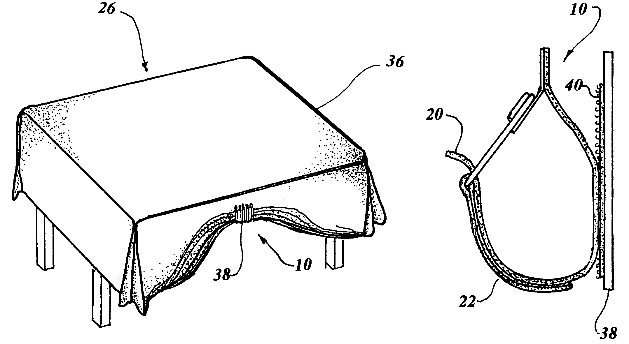
[0011]In the past, tablecloths have been swagged by hand by simply gathering the tablecloth's material and pinning it together with straight or safety pins to create a decorative effect. There has also been a need to easily mount theme decorations on cloth to create a pleasing appearance for festive or special occasions. Therefore, the primary object of the invention is to provide a method of attaching a clip to a fabric without penetrating or damaging the fabric.
[0012]The invention is easily used by attaching the two parts of a garter grip together, one on each side of a tablecloth or other fabric, and looping a pair of straps around a gather to make a swag in the material. The two ends of the straps are attached together with hooks and loops of VELCRO fasteners. The use of the invention is not labor intensive, as is the conventional method of using pins, since the invention contains all of the necessary components to form a swag in a tablecloth quickly and easily, with the swag formed in as little as 20 seconds.
[0013]An important object of the invention is that the clip serves a dual purpose by permitting a tablecloth to not only be gathered into a swag quickly but also to provide a convenient mount for decorative items on a fabric such as curtains, drapes and the like.

Problems solved by technology

Such injury to the user is caused due to the difficulty of using pins that are required to penetrate several thicknesses of fabric, which often causes the pins to painfully the user's fingers.

Method used


Image

  • Fabric attaching clip
  • Fabric attaching clip
  • Fabric attaching clip

Examples


fourth embodiment

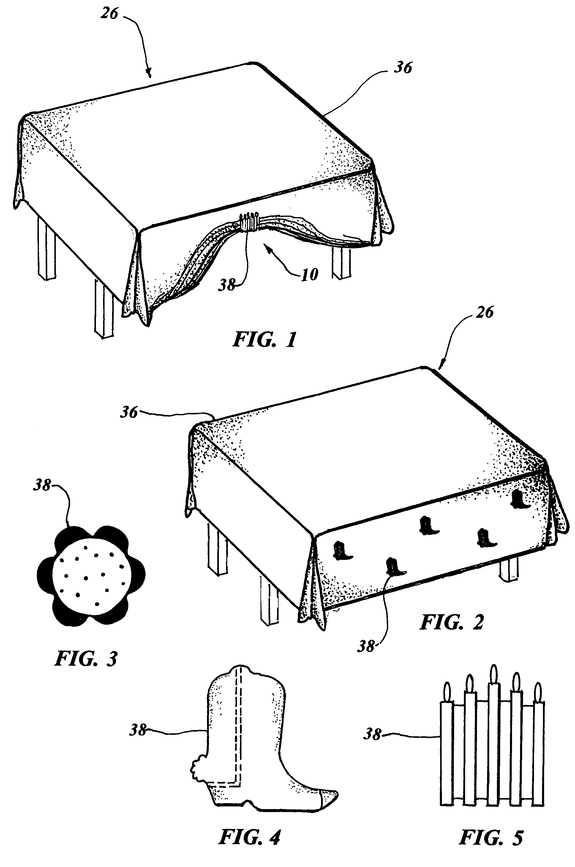
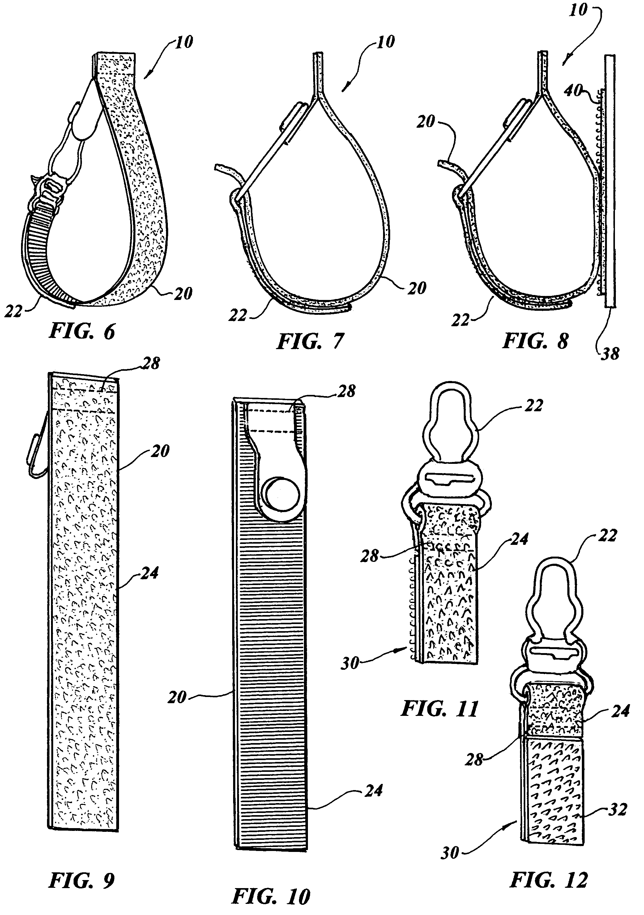
[0056]The best mode for carrying out the invention is presented in terms of a preferred, second, third and fourth embodiment for a fabric attaching clip 10, (hereinafter “FAC 10”). Each embodiment differs only in the method used to attach the invention to a tablecloth or the like. The preferred embodiment of the FAC 10, as shown in FIGS. 1-12, and 26-28, utilizes a garter grip as its basic element. The garter grip is made in two parts: a button end 20 which consists of a flat thermoplastic tab in which a round button is integrally formed, and a wireform 22 which is configured to fit over the button end 20. The wireform 22 has a wide radial shape with a distal end looped in the substantially same diameter as the stem of the button. The garter grip permits the wireform 22 to be placed over the button end 20 with fabric in between. When the wireform 22 is pulled downward the distal end loop engages the stem of the button with the fabric stretched in between, thus forming a secure conne...

second embodiment

[0060]the FAC 10, is shown in FIGS. 13-19 and, like the preferred embodiment, utilizes the garter grip in conjunction with the hook and loop tape, with the garter grip button end 20 attached to a loop tape strap 24 which is positioned on an outer surface of a fabric 26. The assembly of the garter grip button end 20 and loop tape strap 24 is accomplished using stitching 28 to sew the tab of the button end 20 to the loop tape strap 20 on one end, as shown in FIGS. 16 and 17.

[0061]The garter grip wireform 22 is attached to a hook and loop tape strap 30, as shown in FIGS. 18 and 19. The hook and loop tape strap 30 is positioned on an inner surface of the fabric 26 over the garter grip button end 20 which is then tightly engaged with the fabric 26 drawn between with the grip button end 20, and wireform 22. The FAC 10 swags the fabric 26 by gathering the fabric 26 together and encompassing the gathers with the loop tape strap 30. The loop tape strap 24 is joined to the hook side 32 of the...

third embodiment

[0063]the FAC 10, as shown in FIGS. 20-24, employs the same garter grip button end 20 positioned on an outer surface of a fabric 26, with a garter grip wireform 22 positioned on the fabric's 26 inner surface. The garter grip wireform 22 is positioned over the garter grip button end 20 and drawn tightly, thereby engaging the fabric as in the previously discussed embodiments. Means for attaching an article on the outer surface of the fabric 26 adjacent to the garter grip button end 20 is achieved utilizing a single loop tape strap 24 that is located between the garter grip button end 20 and the garter grip wireform 22. Fabric 26 is swagged in this embodiment by manually gathering the fabric 26 together and encompassing the fabric 26 with the loop tape strap 24.

[0064]In the above third embodiment, a decorative tape strap 34 may be substituted for the loop tape strap 24 that is located between the garter grip button end 20 and the garter grip wireform 22, which is used for swagging fabr...


PUM


Abstract

A fabric attaching clip (10) consisting of a garter grip button end (20) attached to a loop tape strap (24) positioned on an outer surface of a fabric (26). A garter grip wireform (22) is attached to a hook and loop tape strap (30) that is positioned on an inner surface of the fabric, aligning with the garter grip button end (20) and tightly engaged with the fabric drawn compressably between. The fabric attaching clip (10) permits fabric, to be swagged by gathering the fabric with the loop tape strap, which has the end threaded into the wireform and by pulling the extending end for adjustment. The loop tape strap (24) is joined to the hook and loop tape strap (30) for closure therebetween. A theme decoration (38) having a hook tape segment (40) is attached on a front surface of the loop tape strap (30), providing both a decorative effect to a table and covering the clip (10).

Description

TECHNICAL FIELD[0001]The invention generally pertains to clips for fabric attachment, and more specifically to a clip for swagging tablecloths or mounting an ornamental decoration on any fabric.BACKGROUND ART[0002]Previously, many types of clips have been used to provide an effective means for altering the response of fabric, such as a swag in a drape, or a tablecloth, and to attach items such as decorative renditions of skirts and flowers to a tablecloth.[0003]The prior art listed below did not disclose any patents that possess the novelty of the instant invention, however the following U.S. patents are considered related:[0004]U.S. Pat. No.InventorIssue Date5,275,225Marasco et al.Jan. 4, 19945,287,614EhrlichFeb. 22, 19945,996,190PetersonDec. 7, 19996,477,751Baumdicker et al.Nov. 12, 20026,705,380ScollettaMar. 16, 2004[0005]Marasco et al. in U.S. Pat. No. 5,275,225 discloses a swag support consisting of a rod with a longitudinal slot at the rear. A head portion is mounted in the sl...

Claims


Application Information

Patent Timeline
IPC IPC(8): A44B21/00A44B11/25A44B17/00A44B99/00
CPCA41F11/04Y10T24/44077Y10T24/2708
Inventor NEVENS, SUSAN E.
Owner NEVENS SUSAN E
Learn More