
Ergonomic appliance handle

a technology of ergonomics and handles, applied in the field of handles, can solve the problems of affecting the ergonomics affecting the operation affecting the use of the canister vacuum, so as to achieve the effect of convenient and convenient operation of the vacuum

Inactive Publication Date: 2007-05-15
DECKER DEBORAH
View PDF21 Cites 11 Cited by
  • Summary
  • Abstract
  • Description
  • Claims
  • Application Information

AI Technical Summary

Benefits of technology

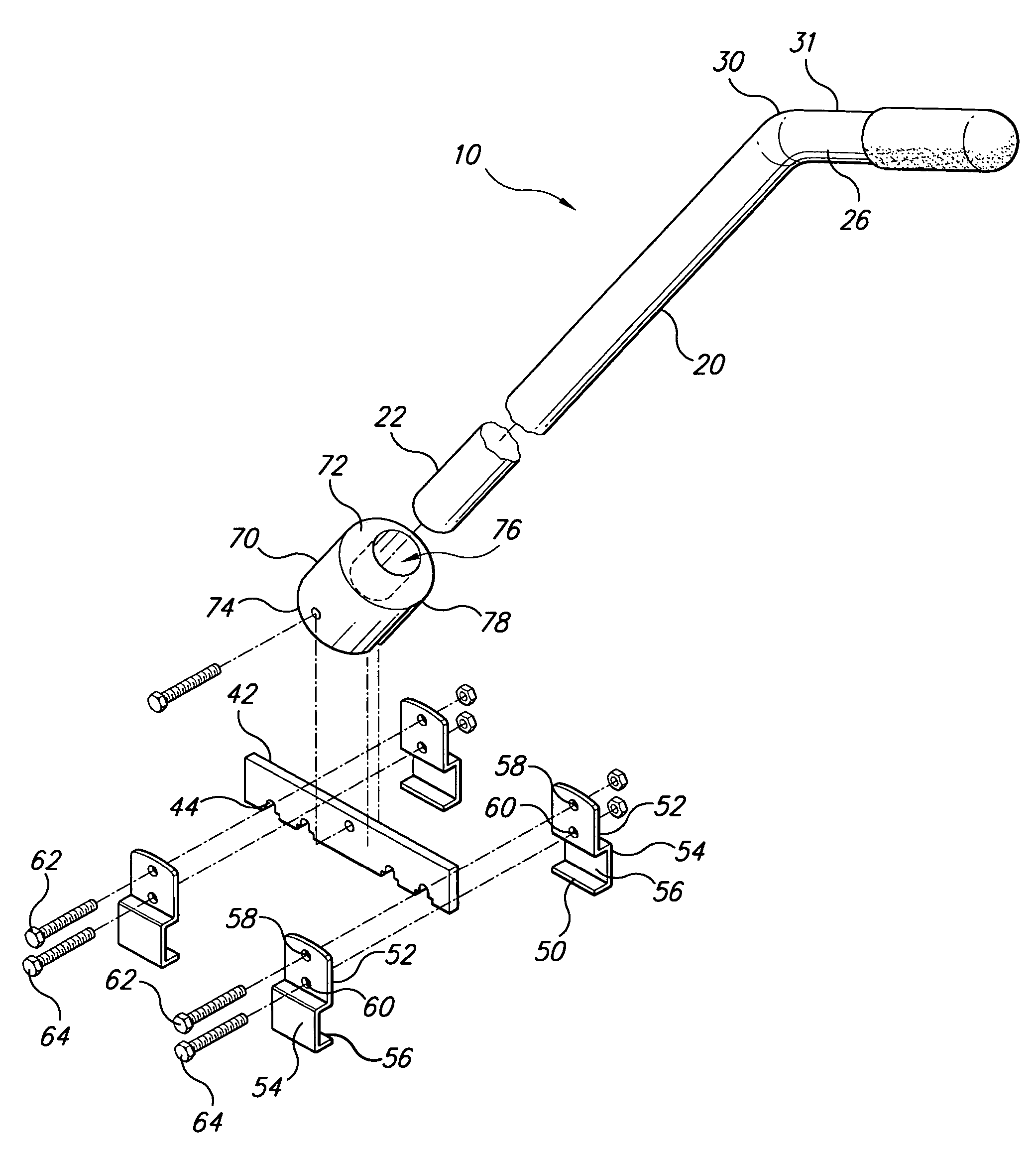
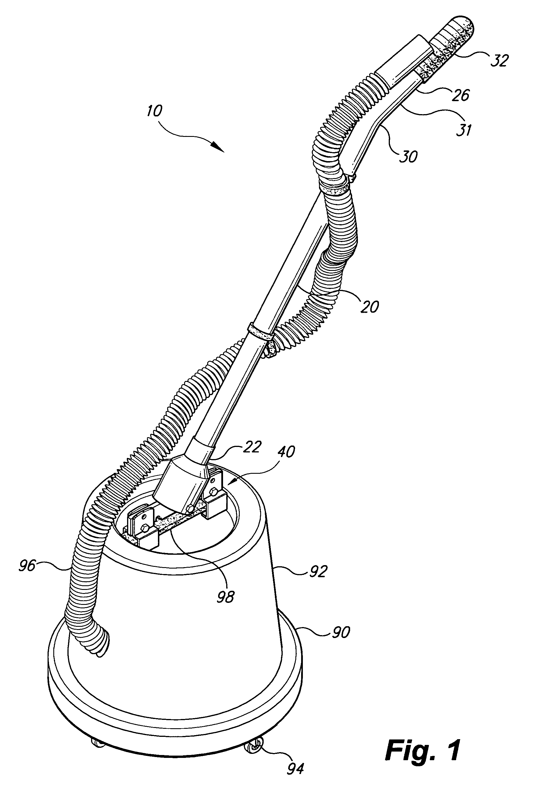
[0023]The ergonomic appliance handle is an extension handle that is attachable to a carrying or transport handle on a vertically oriented canister style vacuum cleaner or similar floor appliance. The ergonomic appliance handle provides an elongated handle shaft that attaches at a proximate end of the handle shaft to the canister vacuum's handle by means of a mounting assembly. The handle shaft extends angled upward and away from the vacuum, placing a handgrip at the distal end of the handle shaft at an ergonomically comfortable height and position for a user to easily and conveniently operate the vacuum in a comfortable posture without subjecting the user to unnecessary bending, stooping, or twisting.
[0024]The ergonomic appliance handle allows a user to maneuver the canister vacuum in an ergonomically correct and safe manner by providing the user the ability to both push and pull the vacuum, to maneuver the vacuum around obstacles and obstructions, to more easily move the vacuum over obstructions in the floor surface such as transitions from one floor surface to another, and to more easily control the movement of the vacuum over an uneven flooring surface, thus eliminating situations that require the user to bend, stoop, or twist.
[0025]The ergonomic appliance handle provides enhanced ergonomic comfort and convenience for a user, thus complementing the advantages, and overcoming the disadvantages, of the canister style vacuum.

Problems solved by technology

During the course of moving a canister vacuum, some situations are encountered that compromise the ergonomic advantage of the canister vacuum.
Such actions place a strain on the user's body and in particular the lumbar-sacral area of the user's lower back.
Additionally, as a canister vacuum is pulled from room to room, or area to area, the canister vacuum's wheels are likely to encounter obstacles such as carpet edges, door thresholds, and the like that prevent further rolling movement of the canister vacuum.
Simply pulling harder on the hose risks pulling the hose free from the main housing, or tipping over the canister vacuum entirely.
Either case requires a corrective intervention by the user to either re-attach the hose, or to upright the canister vacuum, both operations requiring bending and / or twisting by the user that present the potential for back strain and other bodily injury.
The alternative to pulling harder on the hose to overcome the obstruction is to lift the canister vacuum over the obstruction, again risking back strain or other injury.
Also, on certain flooring surfaces the caster wheels may tend to guide the canister vacuum in an erratic path as it is pulled, requiring the user to intervene to prevent the canister vacuum from bumping walls, furniture, and such.
An additional drawback to moving a canister vacuum by simply pulling the canister vacuum along by its hose is that, because the hose is flexible, the canister vacuum cannot be pushed, or maneuvered backwards, by the hose.
Again, user intervention is required that requires the user to bend, stoop, twist, or stretch in a manner that may cause injury.

Method used


Image

  • Ergonomic appliance handle
  • Ergonomic appliance handle
  • Ergonomic appliance handle

Examples


first embodiment

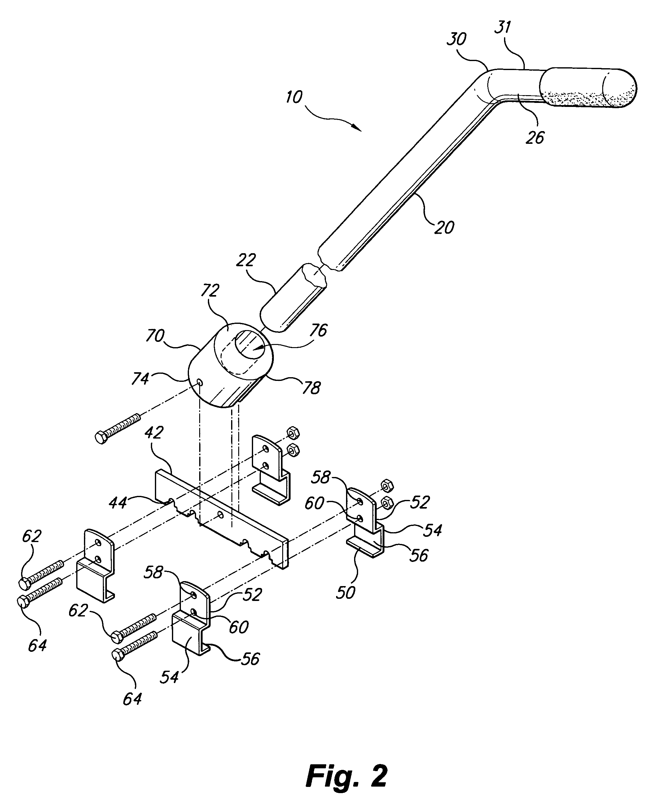
[0037]The present invention is an ergonomic appliance handle. Referring to FIG. 1, an ergonomic appliance handle 10 is shown attached to a carry handle 98 of a typical canister vacuum 90. The canister vacuum 90 illustrated is typical of a variety of vacuum cleaning appliances generally comprising a cylindrical housing 92 disposed vertically on a plurality of wheels 94, some or all of the wheels 94 being pivoting or caster type wheels. The housing 92 contains a motor and vacuum mechanism, and a collection receptacle. A proximal end of a flexible hose 96 is attached to an intake opening defined in the housing 92. At a distal end of the flexible hose 96, a cleaning attachment, accessory, or power nozzle, may be attached. A carry handle 98 is generally disposed atop the housing 92, the carry handle 98 lying generally horizontally as the canister vacuum 90 sits on a horizontal surface, such as a floor.

[0038]The ergonomic appliance handle 10 comprises an elongated shaft 20 having a proxim...

second embodiment

[0046]Turning now to FIG. 4, an ergonomic appliance handle 100 is shown attached to a carry handle 198 of a canister vacuum, the horizontal extent of the carry handle 198 being shorter than the carry handle 98 seen in FIG. 1. The ergonomic appliance handle 100 employs a mounting assembly 140 that is better suited to the shorter carry handle 198.

[0047]Referring to FIG. 5, the mounting assembly 140 of the second embodiment is shown in greater detail. A single pair of brackets 150 straddles the carry handle 198 and holds a coupling fixture 170 attached to the elongated shaft 20. Each of the brackets 150 has a flat upper portion 152 having an arcuate top edge 153. A bottom portion 154 of each bracket 150 is bent into a “C” shape defining a channel 156. An upper aperture 158, and at least one lower aperture 160 (two are shown) are defined in the upper portion 152 of each of the brackets 150. Each at least one lower aperture 160 receives a lower fastener 164 joining and clamping the two b...

third embodiment

[0051]Turning now to FIGS. 8 and 9, an ergonomic appliance handle 400 is shown. The ergonomic appliance handle 400 employs a mounting assembly 440 that allows the angle of the elongated shaft 20 to be varied. The mounting assembly 440 illustrated employs brackets 50 to attach the mounting assembly 440 to the carry handle 98 of a canister vacuum. The brackets 50 support a crossbar 442, the crossbar 442 being similar to the crossbar 42 described above but somewhat wider. A coupling fixture 470 is supported on the crossbar 442.

[0052]The coupling fixture 470 is comprised of two members pivotally joined to one another. A base member 486, mounted to or formed as a unitary part of the crossbar 442, is pivotally joined to a socket member 472 that retains the elongated shaft 20. The socket member 472 has a socket end 474 wherein a cylindrical recess 476 is defined and adapted to receive the proximal end 22 of the elongated shaft 20. A mating portion 478 of the socket member 472 has a general...


PUM


Abstract

The ergonomic appliance handle is an extension handle that is attachable to a carrying or transport handle on a canister style vacuum cleaner or similar floor appliance. The ergonomic appliance handle provides an elongated handle shaft that is attached to the canister vacuum's handle at a proximate end of the handle shaft by a mounting assembly. The handle shaft extends angled upward, away from the vacuum, placing a handgrip at the distal end of the handle shaft at an ergonomically comfortable height and position for a user to easily and conveniently operate the vacuum in a comfortable posture without subjecting the user to unnecessary bending, stooping, or twisting.

Description

BACKGROUND OF THE INVENTION[0001]1. Field of the Invention[0002]The present invention relates to handles and similar attachments for various devices, and more particularly to an ergonomic appliance handle that provides an ergonomic improvement to a vertically oriented canister style vacuum cleaner or other floor appliance.[0003]2. Description of the Related Art[0004]Vertical canister type vacuum cleaners are widespread in use in homes, commercial settings, and many other places. Vertical canister type vacuum cleaners (canister vacuums) generally have a cylindrical main housing disposed vertically on a plurality of wheels, some or all of the wheels being pivoting or caster type wheels. The housing contains a motor and vacuum mechanism, as well as a collection receptacle such as a filter bag, or a bag-less drum or water reservoir. An intake opening and an exhaust opening in the housing are connected to the vacuum mechanism, whereby air, along with dirt, particulate matter, and other o...

Claims


Application Information

Patent Timeline
Patent Type & Authority Patents(United States)
IPC IPC(8): B25G1/00
CPCA47L9/0036A47L9/327B25G1/102Y10T16/498Y10T16/476Y10T16/4713Y10T16/4719
Inventor DECKER, DEBORAH
Owner DECKER DEBORAH
Learn More