
Methods and compositions for introducing conductive channels into a hydraulic fracturing treatment

a technology of conductive channels and hydraulic fracturing, applied in the field of methods, can solve the problems of reducing the efficiency of treatment, reducing productivity, and reducing the efficiency of hydraulic fracturing, and achieve the effect of adversely affecting the permeability of the particulate pack

Inactive Publication Date: 2007-05-08
BAKER HUGHES INC
View PDF38 Cites 77 Cited by
  • Summary
  • Abstract
  • Description
  • Claims
  • Application Information

AI Technical Summary

Benefits of technology

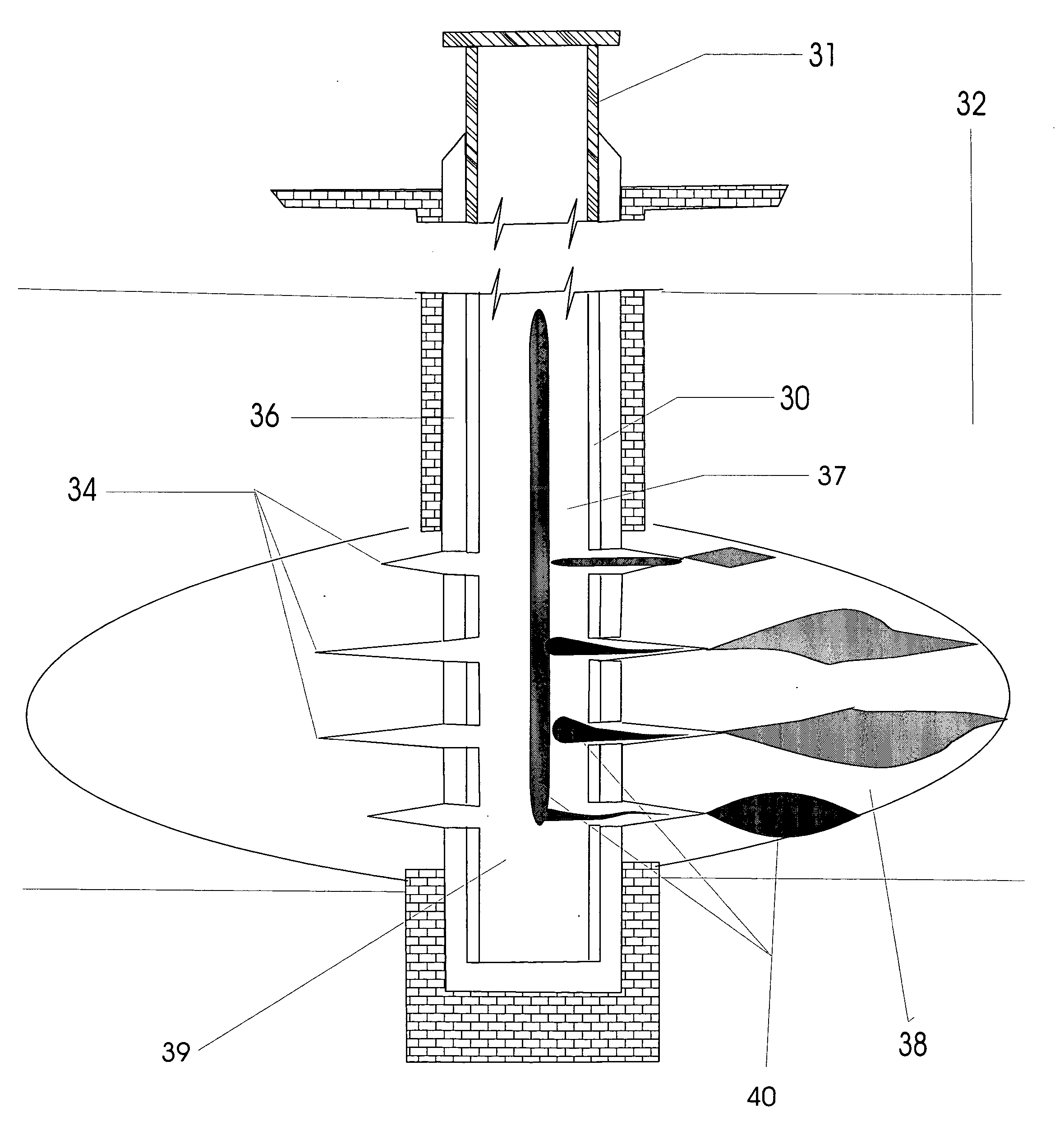
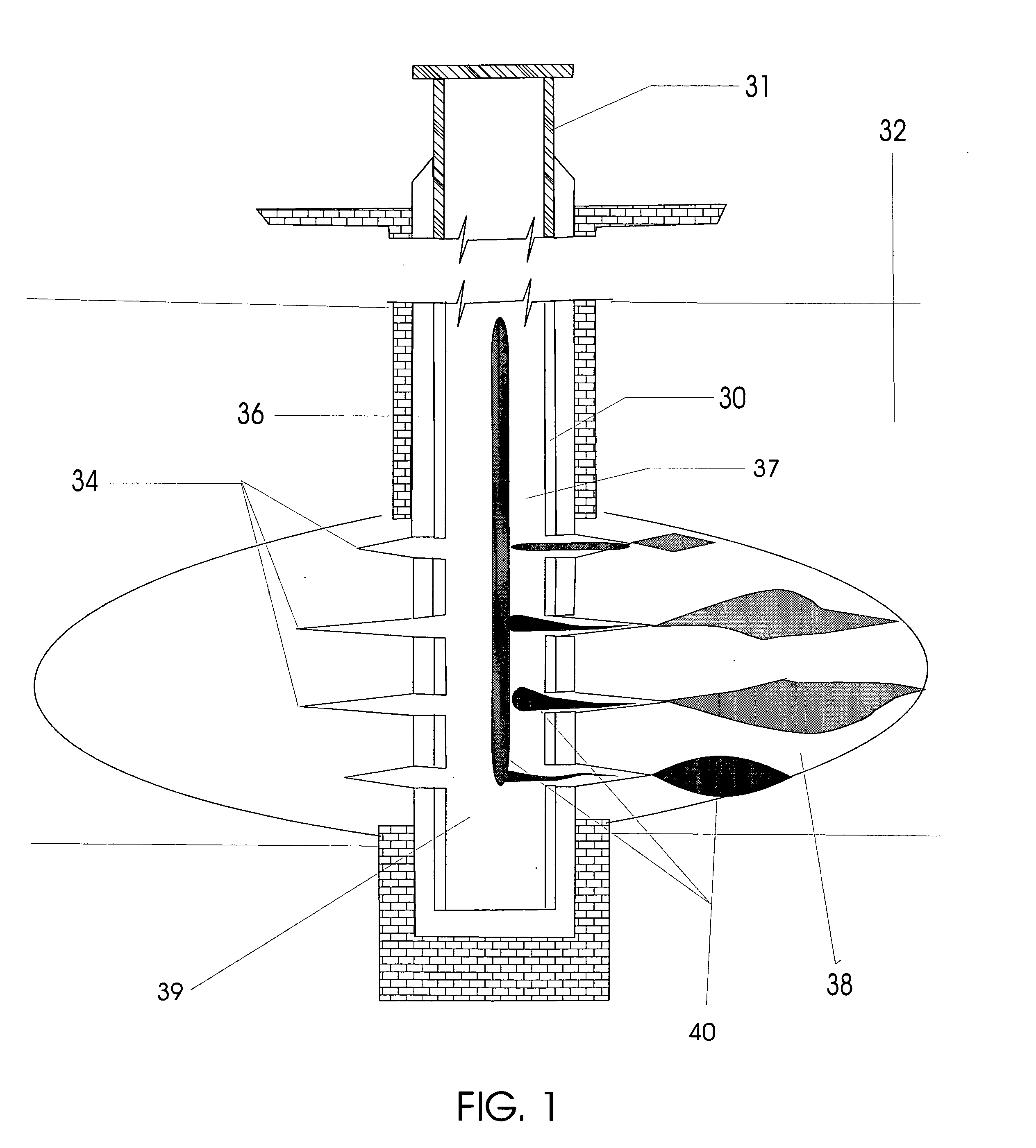
[0016]The present invention provides methods, compositions, and systems for introducing highly conductive channels into a hydraulic fracturing treatment. Such methods and systems also provide a resultant particulate pack that inhibits the flow of particulates back through the wellbore during the production of hydrocarbons without adversely affecting the permeability of the particulate pack.

Problems solved by technology

Hydraulic fracturing is one of the petroleum (oil and gas) industry's most complex operations.
Several problems have become associated with such processes, especially with regard to the placement of propping agents in fractures.
For example, underdisplacement can occur if the fracture is not completely filled with propping agent in the near wellbore region, greatly reducing productivity due to the closure stresses at the mouth of the fracture near the wellbore.
Such problems have been shown to cause the fracture to close upon incomplete fracture fill-up due to the high stress level in the near wellbore region, thereby reducing the effectiveness of the treatment.
Similarly, overdisplacement can occur if too large a volume of propping agent is used, causing proppant to settle in the wellbore itself and cover well perforation, thereby potentially limiting and reducing well productivity.
Perhaps the most common problem associated with hydraulic fracturing, however, is that of proppant flowback following the fracturing treatment.
However, when the proppants themselves are transported back into the wellbore with the production fluids following fracturing, flowback problems arise.
Following a fracture treatment, proppant flowback during cleanup, and over the lifetime of a well, can have many detrimental effects on the success of the treatment, and ultimately on the well itself.
The effects include near wellbore collapse or closure, wells sanding or closing up, and damage to both surface equipment and production facilities by abrasion due to the proppant.
Further problems can include the need for the separation of solids from the produced fluids, and occasional decreases in the efficiency of the fractured operation since the proppant does not remain within the fracture and may therefore limit the size of the created channel.
These problems can in turn lead to reduced or ceased production from a well, increased well production costs, and numerous safety concerns.
These ball sealers seat on the well perforations during the final stages of the fracture, resulting in an increase in surface pumping pressure.
However, these methods generally suffer from having a high cost, and ineffectiveness due to the difficulty in placing such resin-coated proppants uniformly within the fracture and / or the resin coating itself negatively impacting fracture conductivity.
Other problems can arise from undesirable chemical interactions between the resin coating and components of the fracturing fluid itself, such as the crosslinking systems that are commonly employed in the art.
While most all of the above approaches have merits, they all also have a negative impact on production and production costs, and are not always effective or applicable to a range of situations.
Additionally, some flowback control additives, while capable of being successfully applied, carry severe penalties for the retained conductivity of the treated packs, due to the pore volume occupied and their inherent ability to trap migrating fines.
These additives can also seriously impact cleanup and production procedures, and exert an undesirable environmental effect.

Method used


Image

  • Methods and compositions for introducing conductive channels into a hydraulic fracturing treatment
  • Methods and compositions for introducing conductive channels into a hydraulic fracturing treatment
  • Methods and compositions for introducing conductive channels into a hydraulic fracturing treatment

Examples


example 1

Fracture Conductivity Apparatus

[0071]Two different fracture conductivity apparatus was used to experimentally emulate and verify the relationship between fluids of varying viscosity and / or density in a subterranean system. The first slot cell was cylindrical, approximately 6-feet (1.83 m) long and 2-feet (0.61 m) wide, constructed of 1-inch (2.54 cm) thick Plexiglas™ (see FIG. 3A, and FIGS. 4–6). As shown in FIG. 3A, the proximal end 10 of the cell 1 contained an injection port 14 and a septum 12, while the opposite, distal end 16 of the cylindrical cell had an exit port 18 which could be manually controlled. Fluids were pumped through the cell using air-driven accumulator style pumps.

[0072]The second fracture conductivity apparatus / slot cell was constructed in order to visually study the effects of the embodiments of the present invention in a simulated, downhole environment. The visualization cell was constructed of transparent Plexiglas™ sheets that were ½ inch (1.27 cm) thick, c...

example 2

Fracture Model Producing Upwardly Directing Perforations

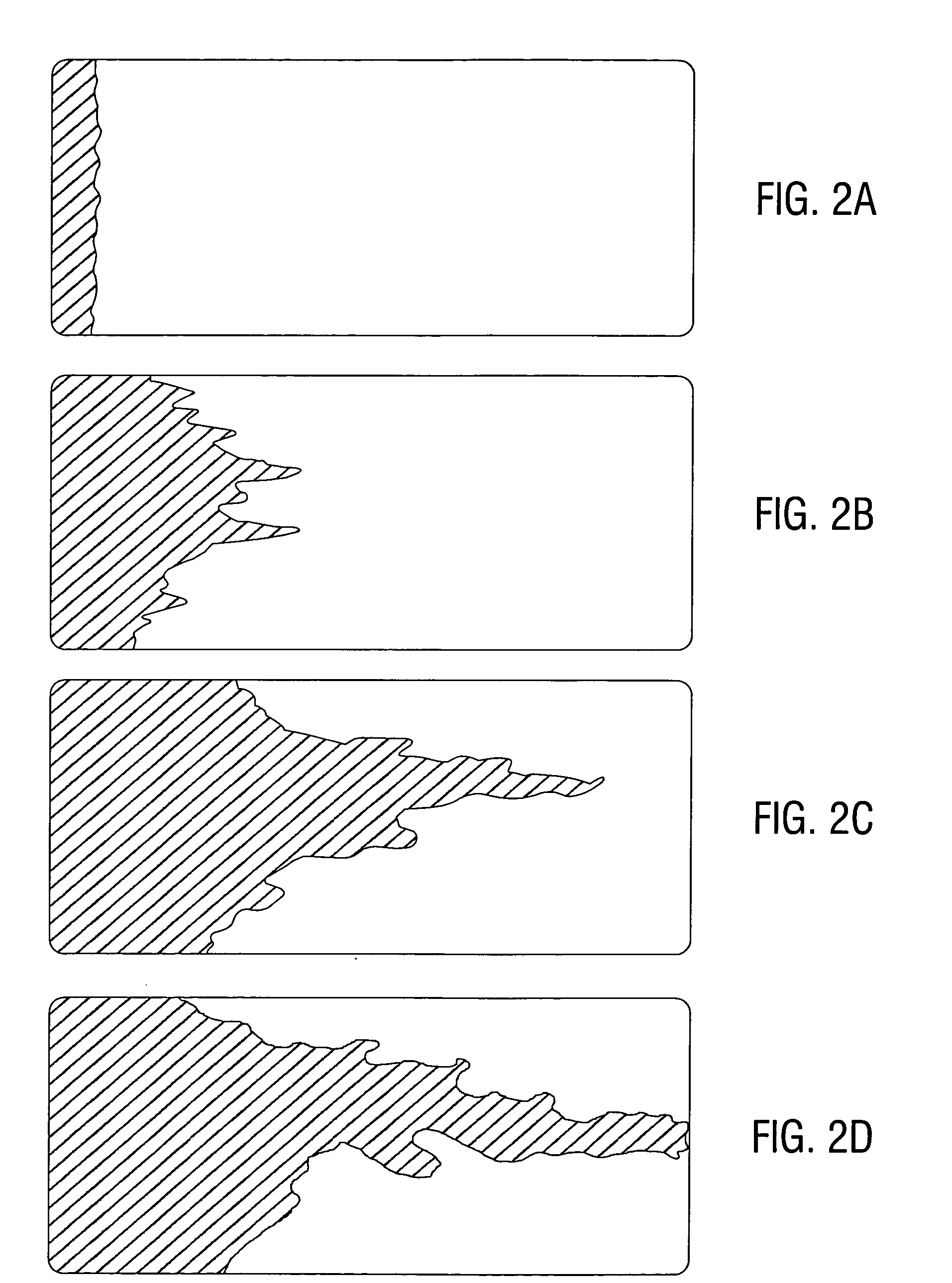
[0074]The fracture cell shown in FIG. 3A was pumped full of a first fracturing fluid, 40 lb Low pH Medallion (BJ Services Company, Houston, Tex.), using a standard low-pressure reservoir air pump system, at a constant pressure of 15 psi (101 kPa). A second fracturing fluid, Super Rheo-Gel (BJ Services Company, Houston, Tex.) containing bauxite proppant, was then pumped into the fracture cell using the same pump system, at a pressure of 15 psi. As the Rheo-Gel flowed through the cell, it created a perforation that gradually sloped upwards, as shown in FIG. 3. This perforation created by the two fracturing fluids exhibited no apparent intermixing of the fluids at their interfaces.

example 3

Fracture Model Producing Downwardly Directing Perforations

[0075]The fracture cell shown in FIG. 3A was pumped full of a first fracturing fluid, 40 lb Low pH Medallion (BJ Services Company, Houston, Tex.), using a standard low-pressure reservoir air pump system, at a constant pressure of 15 psi (101 kPa). A second fracturing fluid, 40 lb SpectraFrac (BJ Services Company, Houston, Tex.) containing 6 psa (pounds sand added) was then pumped into the fracture cell at a constant pressure of 15 psi (101 kPa). As the Spectra-Frac flowed through the cell, it created a viscous finger that gradually sloped downwards, as shown in FIG. 5. This viscous finger created between the two fracturing fluids had no intermixing of the fluids at their interfaces.


PUM

PropertyMeasurementUnit
densityaaaaaaaaaa
densityaaaaaaaaaa
densityaaaaaaaaaa

Abstract

Methods for the treatment of subterranean wells involving injecting a first fracturing fluid into a formation, and then injecting at least a second fracturing fluid into the formation in order to create extended conductive channels through a formation are described. The fracturing fluids can be similar in density, viscosity, pH and the other related characteristics. Alternatively, the fracturing fluids can differ in their densities, viscosities, and pH, allowing for variations in the conductive channels formed. Propping agents can also be included in one or both of the injected fluids, further enhancing the conductive channels formed. The described methods aid in minimizing proppant flowback problems typically associated with hydraulic fracturing techniques.

Description

FIELD OF THE INVENTION[0001]Methods for the treatment of subterranean wells involving injecting a first fracturing fluid into a formation, and then injecting at least a second fracturing fluid into the formation in order to create extended conductive channels through a formation. The fracturing fluids can be similar in density, viscosity, pH and the other related characteristics. Alternatively, the fracturing fluids can differ in densities, viscosities, and pH, allowing for variations in the conductive channels formed. Propping agents can also be included in one or both of the injected fluids, further enhancing the conductive channels formed.BACKGROUND OF THE INVENTION[0002]Hydraulic fracturing is one of the petroleum (oil and gas) industry's most complex operations. Applied in an effort to increase the well productivity, in a typical procedure fluids containing propping agents are pressurized and pumped into a well at pressures and flow rates high enough to split the rock and creat...

Claims


Application Information

Patent Timeline
Patent Type & Authority Patents(United States)
IPC IPC(8): E21B43/267C09K8/62C09K8/80E21B43/26
CPCC09K8/62C09K8/80E21B43/267
Inventor BRANNON, HAROLD DWOOD, WILLIAM DSTEPHENSON, CHRISTOPHER J
Owner BAKER HUGHES INC
Learn More