
Pacing optimization based on changes in pulse amplitude and pulse amplitude variability

a technology of pulse amplitude and variability, applied in the field of monitoring cardiac performance, can solve the problems of increasing perioperative morbidity and mortality, limiting system accuracy, and involving patients in intramyocardial instrumentation

Inactive Publication Date: 2007-04-17
PACESETTER INC
View PDF20 Cites 81 Cited by
  • Summary
  • Abstract
  • Description
  • Claims
  • Application Information

AI Technical Summary

Problems solved by technology

However, both the amount and the sophistication of the objective physiological data that can be acquired in this way are quite limited, which consequently limits the accuracy of the system.
However, intravascular or intramyocardial instrumentation carries significant risks to the patient, including increased perioperative morbidity and mortality, and increased long-term risks such as stroke and pulmonary embolism.
Furthermore, intravascular instrumentation can only be performed by extensively trained specialists, thereby limiting the availability of qualified physicians capable of implanting the device, and increasing the cost of the procedure.
Finally, because of the added patient risks and greater physical demands of an intravascular environment, the intravascular placement of the sensor increases the cost of development, manufacturing, clinical trials, and regulatory approval.
Both these approaches require surface contact electrodes which are cumbersome and inconvenient for the patient, and more susceptible to motion artifact than an implanted electrode.
Thus the Reveal is intended for short-term recording for diagnostic use, is limited to recording the electrical activity of the heart, and does not attempt to measure or quantify the hemodynamic status of the patient beyond screening for cardiac arrhythmias.
While the Holter monitor recorder, the Reveal Insertable Loop Recorder, and the Implantable Ambulatory Electrocardiogram Monitor provide important clinical utility in recording and monitoring cardiac electrical activity, none is designed to monitor hemodynamic status.
Indeed, cardiac electrical activity does not, by itself, provide unambiguous information about hemodynamic status.
By sensing only cardiac electrical activity, these devices are unable to distinguish between, for example, a hemodynamically stable cardiac rhythm and Pulseless Electrical Activity (PEA), a condition in which the heart is depolarizing normally, and thus generating a normal electrical pattern, but is not pumping blood.
Furthermore, these devices are unable to recognize or quantify subtle changes in the patient's hemodynamic status.
The technical challenge is made more difficult by the greatly increased circumference, relative to that of standard feed-through connections known in the art, of the boundary between the window and the device housing.
While this is an obvious solution for devices that have external leads requiring headers, it presupposes the existence of a header, and therefore does not address the implantable device that lacks a header.
Furthermore, while appending a header to one end or pole of an implantable device is an efficient solution when external leads are required, appending a header-like sensor unit to one end or pole of a device not otherwise requiring a header, where the sensor unit is itself, like a header, the full-thickness of the device, is an inefficient use of volume.
Thus, the approach of Prutchi et al. used in a device that doesn't otherwise require a header would be to append a header or a header-like sensor unit to one end or pole of the device, but this would unnecessarily increase both the volume and the expense of the device.
A further disadvantage of placing a sensor in a header is that it does not necessarily provide for the optimal signal transduction of a particular sensor.
For example, the performance of the optical sensor described in the above referenced U.S. Pat. No. 5,556,421 would be so severely degraded by direct transmission of light from source to detector that one skilled in the art would question the functionality of the proposed solution.
In addition, placement in a rigid epoxy header is simply not an option for some sensors, such as sound sensors, because of the dramatic degradation in the signal-to-noise ratio the rigid header would impose.

Method used


Image

  • Pacing optimization based on changes in pulse amplitude and pulse amplitude variability
  • Pacing optimization based on changes in pulse amplitude and pulse amplitude variability
  • Pacing optimization based on changes in pulse amplitude and pulse amplitude variability

Examples


Embodiment Construction

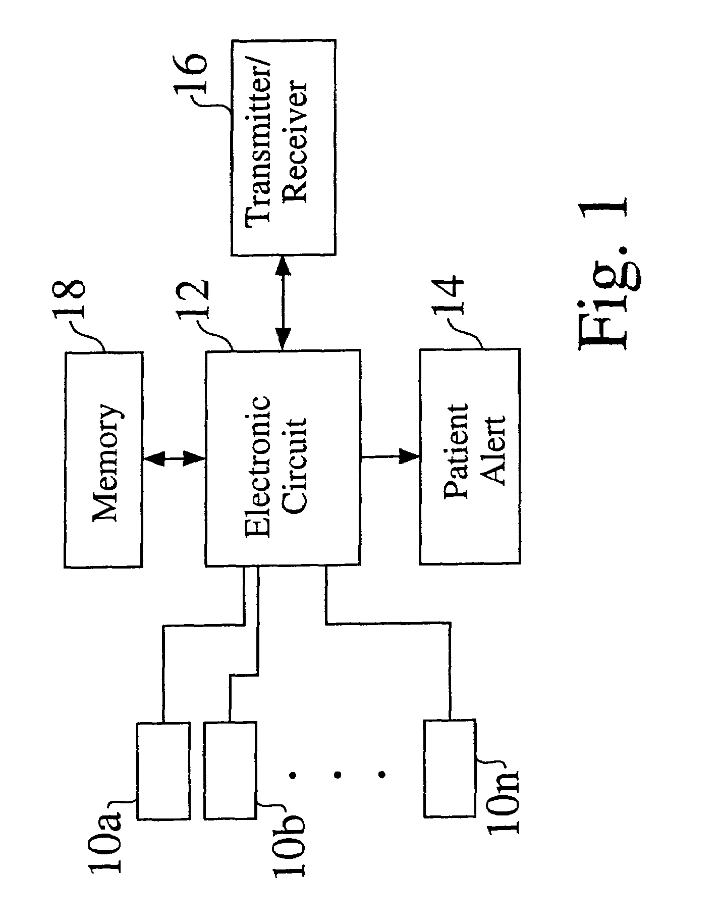
[0040]A functional block diagram of a monitor according to an embodiment of the present invention is shown in FIG. 1. One or a plurality of sensors 10a, 10b, . . . 10n is connected to an electronic circuit 12, which in turn is connected to a patient alert 14, transmitter / receiver 16, and memory 18, with each of elements 14, 16 and 18 being optional. In an embodiment, the electronic circuit 12 includes a low-power microprocessor. In alternate embodiments the microprocessor is excluded, or control and higher level processing is performed by a microcontroller, an embedded system, a programmable logic device such as a field-programmable logic array, or a combinatorial implementation of a state machine. In an embodiment the transmitter / receiver 16 is an integrated radio frequency telemetry unit. Other embodiments of the transmitter / receiver are possible, including acoustic, optic, electrostatic, and magnetic. In yet another embodiment the receiver is simply a reed switch capable of sensi...


PUM


Abstract

A signal indicative of cardiac contractions of a patient's heart is produced, as the patient's heart is paced using different sets of pacing interval parameters. Measures of pulse amplitude are obtained from the signal. Pacing interval optimization is performed based on the measures of pulse amplitude.

Description

PRIORITY CLAIM[0001]This application is a continuation-in-part of U.S. patent application Ser. No. 10 / 208,081 filed Jul. 29, 2002 (now U.S. Pat. No. 6,942,622), which is a continuation-in-part of U.S. patent application Ser. No. 09 / 467,298, filed Dec. 17, 1999 (now U.S. Pat. No. 6,480,733), which is a continuation-in-part of application Ser. No. 09 / 438,017, filed Nov. 10, 1999 (now U.S. Pat. No. 6,409,675), each of which is incorporated herein by reference.FIELD OF THE INVENTION[0002]Embodiments of the present invention relate to monitoring cardiac performance, as well as performing pacing optimization based on monitored cardiac performance.BACKGROUND OF THE INVENTION[0003]The multiplicity of feedback mechanisms that influence cardiac performance places the heart at the center of a complex control network. The neurohumoral axis includes the autonomic nervous system, consisting of sympathetic and parasympathetic branches, and numerous circulating hormones such as catacholamines, angi...

Claims


Application Information

Patent Timeline
Patent Type & Authority Patents(United States)
IPC IPC(8): A61N1/362
CPCA61B5/02405A61B5/02416A61B5/14552A61B5/4035A61B7/04A61N1/36585A61N1/3627A61N1/3682
Inventor TURCOTT, ROBERT
Owner PACESETTER INC
Learn More