Optical transmitter and optical communication system

a technology of optical communication system and optical transmitter, which is applied in the field of optical transmitter, can solve the problems of extremely degraded optical signal and still remain the problems above mentioned, and achieve the effect of reducing the deterioration of transmitted optical signal

Active Publication Date: 2007-03-27
SUMITOMO ELECTRIC IND LTD
View PDF4 Cites 9 Cited by
  • Summary
  • Abstract
  • Description
  • Claims
  • Application Information

AI Technical Summary

Benefits of technology

[0006]The present invention provides an optical transmitter that reduces a deterioration of transmitted optical signal at a receiving station due to elongation of an optical path, and an optical communication system that uses the optical transmitter.

Problems solved by technology

However, when the optical signal is extremely degraded, problems above mentioned still remain.

Method used


Image

  • Optical transmitter and optical communication system
  • Optical transmitter and optical communication system
  • Optical transmitter and optical communication system

Examples


first embodiment

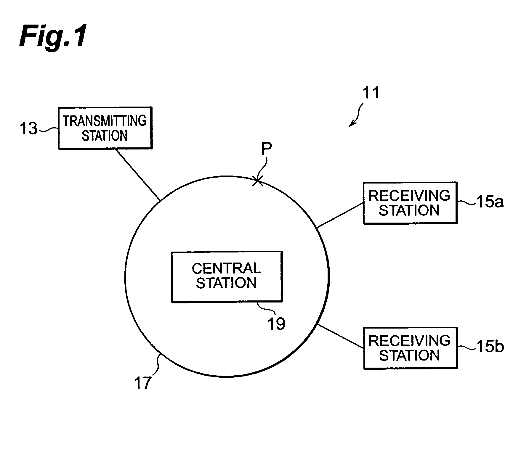
[0020]An optical communication system 11 according to the present invention is schematically shown in FIG. 1. The optical communication system 11 comprises a transmitting station 13, a receiving station 15, an optical path 17 and a central station 19. The transmitting station 13 involves an optical transmitter. The receiving station 15 involves an optical receiver. The optical path 17 has a ring-shaped configuration and may be an optical fiber.

[0021]The central station 19 checks faults occurred on the optical path 17 and traffic of the optical signal transmitted on the optical path 17. The station 19 sends information of the selection of the receiving station to the transmitting station 13, the route to the selected receiving station, and a dispersion amount of the selected route to the transmitting station.

[0022]In FIG. 1, one occasion is considered that the optical path 17 is broken at point P when the transmitting station 13 sends information to the receiving station 15a via a cl...

second embodiment

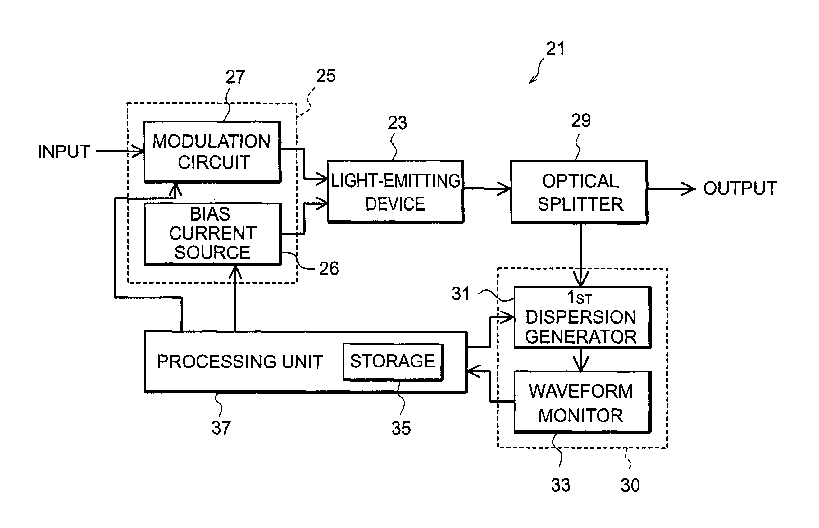
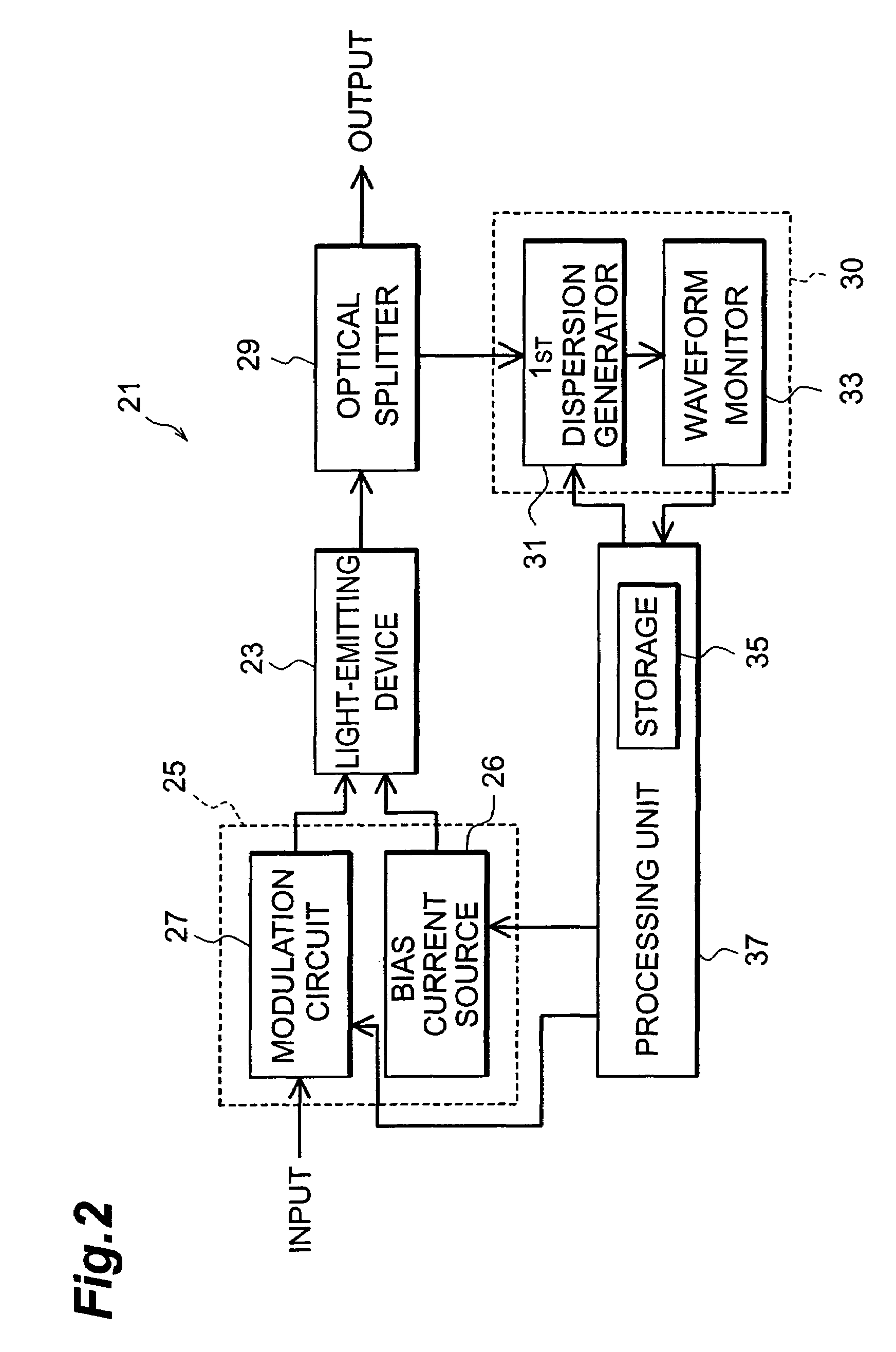
[0032]FIG. 6 shows a block diagram of an optical transmitter 121 according to the second embodiment of the present invention. The optical transmitter 121 is different to the first embodiment in a point that the second transmitter has a second dispersion generator 28 between the light-emitting device 23 and the optical splitter 29. The second dispersion generator 28 adds dispersion to light output from the light-emitting device 23 and output thus dispersed light to the optical splitter 29.

[0033]The optical splitter 29 splits light into two portions, one of which is guided to the first dispersion generator 31. The dispersion amount instructed by the central station 19 is preset to the first dispersion generator. The first dispersion generator adds the preset dispersion to the split light and output thus dispersed light to the waveform monitor 33.

[0034]The waveform monitor 30 inspects the input light signal as an eye-diagram and the processing unit 37 checks whether this eye-diagram ha...


PUM


Abstract

The optical transmitter has a feature that the transmitter comprises a light-emitting device, an optical splitter, a dispersion controller including a first dispersion generator and a waveform monitor, and a processing unit. The optical splitter splits light emitted from the light-emitting device, and guides one of split light into the first dispersion generator. The first dispersion generator adds dispersion, an amount of which is predefined by the processing unit so as to reflect dispersion of the optical path to the receiving station, to the split light and outputs dispersed light to the waveform monitor. The processing unit maintains the dispersed light output from the dispersion generator to have a predetermined quality.

Description

BACKGROUND OF THE INVENTION[0001]1. Field of the Invention[0002]The present invention relates to an optical transmitter and relates to an optical communication system containing such optical transmitter.[0003]2. Related Background Art[0004]A wavelength division multiplexing (WDM) system achieves high speed and high capacity communications by multiplexing a plurality of optical signals with different wavelengths on single optical fiber or the like. In the WDM system, the transmission route from a transmission station to a receiving station sometimes changes due to, for example, a breaking of the optical fiber or a switching of the receiving station, which causes to change the transmission distance. Since the elongation of the transmission distance results in a reduction of an optical signal and a deterioration of the waveform received at the receiving station, optical amplifiers to compensate the signal reduction are provided in the transmission path. Moreover, a plurality of decisio...

Claims


Application Information

Patent Timeline
Patent Type & Authority Patents(United States)
IPC IPC(8): H04B10/04H04B10/12H04B10/18H04B10/24
CPCH04B10/25137H04B2210/254
Inventor OOMORI, HIROTAKA
Owner SUMITOMO ELECTRIC IND LTD
Why Eureka
Try Eureka