
Method for navigating in a multi-scale three-dimensional scene

Inactive Publication Date: 2007-03-13
SCHLUMBERGER TECH CORP
View PDF15 Cites 54 Cited by
  • Summary
  • Abstract
  • Description
  • Claims
  • Application Information

AI Technical Summary

Problems solved by technology

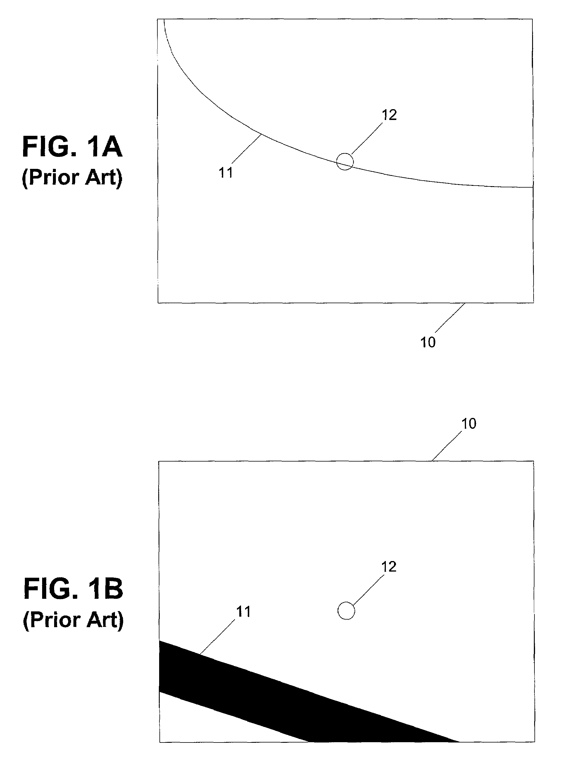
However, due to the imperfection of mapping a 3D object onto a 2D display, the POI is often not placed on the 3D object.
Such imperfection results in a separation (offset) between the POI and the 3D object.
The offset is usually insignificant and unnoticeable initially.
As a result, the region of interest on the 3D object will be displaced to the side of the viewing area, or completely lost from the viewing area after rotation or zooming.
The same problem can also occur in a rotation operation because of the change in the viewing angle.
This extra step can be annoying and time consuming, especially when frequent zoom and rotation operations are performed on the 3D object.
This method reduces the possibility that the POI will be placed outside of the 3D object.
However, these guide lines and planes do not always map the cursors onto the 3D object.
In order to locate and observe a small area in detail, a user needs to zoom in and zoom out of the scene often, and the problem illustrated in FIG. 1B will occur frequently using the existing display tools.
Another issue is that most display tools perform the user-requested operations with the same amounts of motion regardless of how close or how far away the viewer is to the object.
This mode of operation makes it difficult to move the viewpoint accurately in the neighborhood of the object while having a reasonable speed of response when far from it.

Method used


Image

  • Method for navigating in a multi-scale three-dimensional scene
  • Method for navigating in a multi-scale three-dimensional scene
  • Method for navigating in a multi-scale three-dimensional scene

Examples


Embodiment Construction

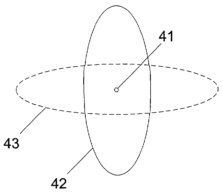
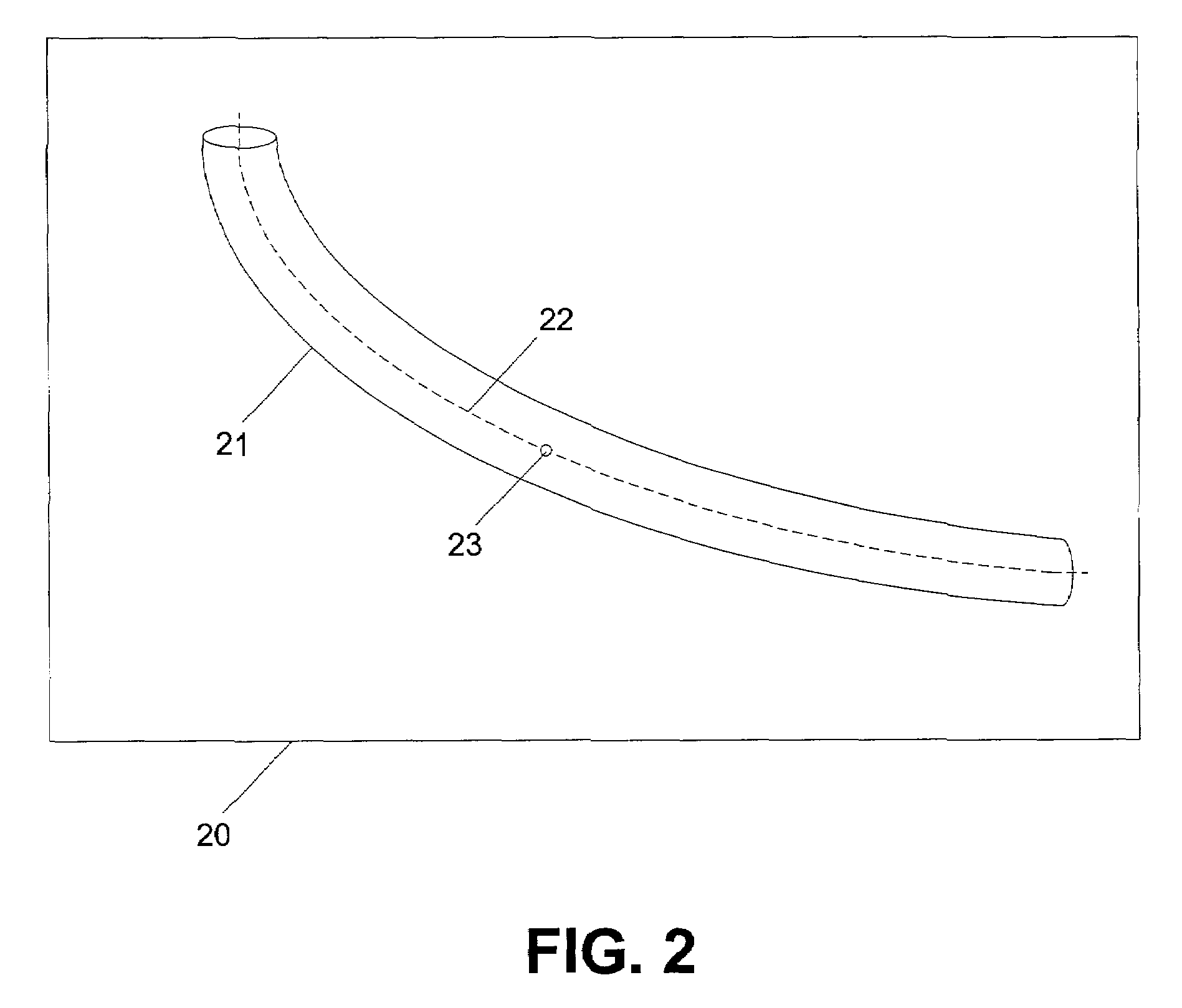
[0021]Embodiments of the present invention relate to user-friendly 3D displays. The embodiments use reference shapes, which track the shapes of the 3D objects under observation, to limit the movement of the points of interest (POI) in performing the user-requested operations (translation, rotation, and zooming). The reference is related to the 3D object in a sense that it may have a shape similar to that of the 3D object and / or its dimension may track that of the 3D object. Furthermore, the coordinates of the reference shapes are linked with the corresponding 3D objects such that they move in concert on the 3D displays. These embodiments are most suitable for, but not limited to, displaying 3D objects that have disproportionate dimensions, e.g., the trajectory of an oil well, which typically spans up to a mile in length and yet has a diameter less than one foot. Such disproportionate dimensions make it necessary for a user to frequently zoom out to keep track of the orientation and ...


PUM


Abstract

A method for navigating a 3D scene in a viewing area includes associating a point of interest with a reference shape, which is related to the shape of the 3D object, and displaying a scene according to a user-requested action, while keeping the point of interest within the reference shape and within the viewing area. The user-requested action may include translation, rotation, and zooming. The point of interest may include scene information such as a magnification factor, local orientation, and global orientation. The methods for performing a user-requested action in a 2D representation of a 3D object include determining a distance between a point of interest and a viewpoint; determining an amount of movement from a user input; and performing the user-requested action at a rate based on the amount of movement from the user input multiplied by a distance factor based on the distance between the point of interest and the viewpoint. A system for displaying a 3D object includes a 2D display for displaying the 3D object and a computer operatively coupled to the 2D display, the computer having a program to display the 3D object on the 2D display, the program adapted to enable translation, zoom, and rotation of the representation while restricting a point of interest within a reference shape and within a viewing window on the 2D display.

Description

FIELD OF THE INVENTION[0001]The present invention relates to techniques for navigating a three-dimensional scene on a display.BACKGROUND OF THE INVENTION[0002]Three-dimensional (3D) objects are commonly represented on computer displays in two dimensions (2D). Such computer displays allow users to view the 3D objects by rotating, translating, or zooming in and out of the displayed scenes. The rotation, translation, and zooming will be referred to generally as a user-requested action (i.e., the user-requested action as used herein refers to “motions” and does not include color / lighting changes or texture mapping changes). Most prior art 3D visualization software packages respond to the user-requested actions by moving the viewpoint (observer eyes or camera) around a 3D scene. For rotation and zooming operations, these are performed with respect to a pivot point, which is typically the point of interest (POI). The POI is either set at the center of the display by default or is selected...

Claims


Application Information

Patent Timeline
IPC IPC(8): G06T15/10G09G5/00G06F3/033G06F3/048G06T19/00
CPCG06F3/04815G06T19/003G06F3/04845G06F2203/04806
Inventor FLEURY, SIMON G.
Owner SCHLUMBERGER TECH CORP
Learn More