Localized lubrication of syringe barrels and stoppers

a technology applied in the field of localized lubrication of syringe barrels and stoppers, can solve the problems of the entire inside surface of the tubular barrel, the amount of silicone applied to the syringe barrel and the stopper exceeds what is required to sufficiently reduce the friction between the two parts, and achieves the effect of reducing friction

Inactive Publication Date: 2007-03-06
BECTON DICKINSON & CO
View PDF15 Cites 15 Cited by
  • Summary
  • Abstract
  • Description
  • Claims
  • Application Information

AI Technical Summary

Benefits of technology

[0007]A medical syringe assembly for administering an injectable drug includes a tubular barrel having an inner wall. A plunger includes a stopper having an engagement surface in slidable engagement with the surface of the inner wall of the tubular barrel. A lubricant is disposed over a limited area of at least one portion of the inner wall of the tubular barrel and the engagement surface of the stopper whereby a sufficient amount of the lubricant is available to adequately reduce friction between the surface of the inner wall of the tubular barrel and the engagement surface of the stopper.

Problems solved by technology

This generally results in the entire inside surface of the tubular barrel being covered with silicone.
In this case, the resultant amount of silicone applied to the syringe barrel and the stopper exceeds what is required to sufficiently reduce the friction between the two parts to a suitable level.

Method used


Image

  • Localized lubrication of syringe barrels and stoppers
  • Localized lubrication of syringe barrels and stoppers

Examples


Embodiment Construction

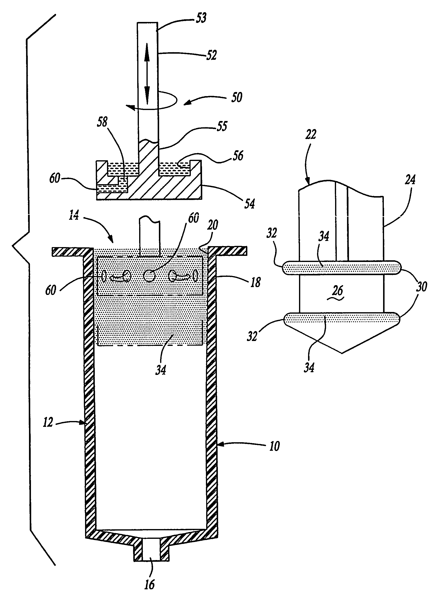
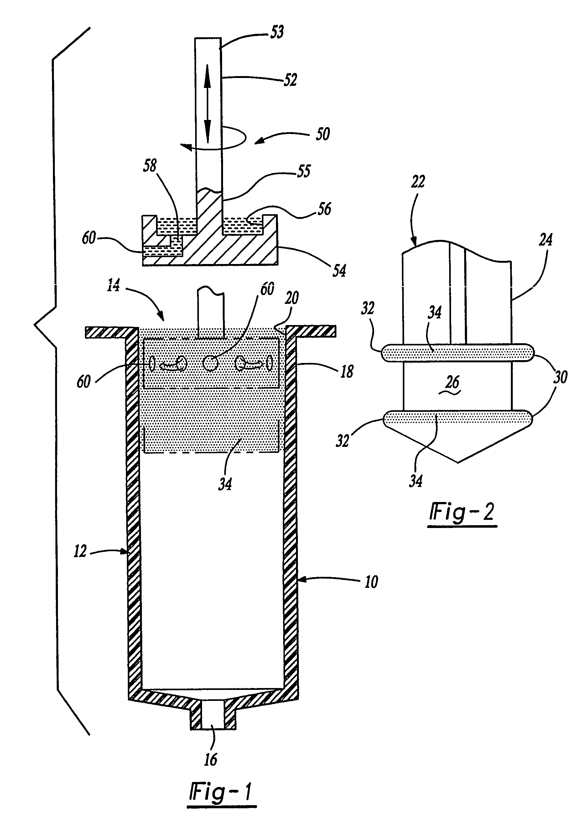
[0014]Referring to the Figures, wherein like numerals indicate like and corresponding parts throughout the several views, a medical syringe assembly is shown generally at 10. The syringe assembly 10 is of the type to be utilized for the administration and injection of injectable drugs.

[0015]The syringe assembly 10 includes a generally cylindrical or tubular barrel 12 having a mouth opening 14 disposed at one end and an outlet 16 disposed at the opposite end. A continuous circumferential wall 18 defines the tubular barrel 12. A lubricant 34 is disposed on a portion of an inner surface 20 of the wall 18. The lubricant 34 is preferably only disposed over a limited area of the inner surface 20 of the tubular barrel 12.

[0016]Referring specifically to FIG. 2, a plunger 22 includes a shaft portion 24 having a stopper 26 disposed at its distal end. The stopper 26 is preferably constructed of an elastomeric material such as a synthetic rubber which conforms to the dimensions of the barrel 12...


PUM


Abstract

A medical syringe assembly includes a first opening and a second opening at opposite ends of a tubular barrel having an inner wall. The inner wall includes an inner surface. A stopper having an engagement surface is slidably received in the tubular barrel and includes a portion for engaging the surface of the inner wall of said tubular barrel. A lubricant is disposed over a limited area of at least one member of the inner wall of the tubular barrel and the engagement surface of said stopper, whereby a sufficient amount of the lubricant is available to provide adequate reduction of friction between the surface of the inner wall of the tubular barrel and the engagement surface of the stopper.

Description

TECHNICAL FIELD[0001]This application is a continuation of U.S. patent application Ser. No. 09 / 494,583, filed on Jan. 31, 2000, now U.S. Pat. No. 6,663,603 now allowed, which is a continuation of U.S. patent application Ser. No. 09 / 092,757, filed on Jun. 5, 1998, now U.S. Pat. No. 6,093,175, both of which are incorporated herein by reference. The subject invention relates to medical syringes and, more specifically, to the lubrication of syringe barrels and stoppers.BACKGROUND OF THE INVENTION[0002]By way of background, syringes typically include a tubular barrel portion and a plunger having a stopper disposed at one end. The plunger and stopper are inserted into the tubular barrel of the syringe. The stopper portion is typically made of an elastomeric material such as natural or synthetic rubber, which engages an inner surface of the syringe tubular barrel to create a seal that facilitates ejecting a fluid from the syringe when pressure is applied to the plunger.[0003]Traditionally,...

Claims


Application Information

Patent Timeline
Patent Type & Authority Patents(United States)
IPC IPC(8): A61M5/315A61M5/31
CPCA61M5/31513A61M2005/3131B05B13/0636
Inventor GYURE, SANDORSPRIECK, TERRY L.SCHMITT, DUANE L.
Owner BECTON DICKINSON & CO
Why Eureka
Try Eureka