
Spinning reel sounding mechanism

a spinning reel and sounding mechanism technology, applied in the direction of reels, applications, fishing, etc., can solve the problems of large fluctuations in the rotational torque of the spinning reel as sound is produced, and the inability to obtain clear, crisp sounds, etc., to achieve smooth rotation, clear, crisp sounds

Inactive Publication Date: 2007-02-13
SHIMANO INC
View PDF21 Cites 13 Cited by
  • Summary
  • Abstract
  • Description
  • Claims
  • Application Information

AI Technical Summary

Benefits of technology

The present invention provides a sounding mechanism for a spinning reel that allows for smooth rotation of the spool and clear, crisp sounds to be obtained. The mechanism includes a first sounding portion and a second sounding portion that are non-rotatable with respect to the spool and spool shaft. The first sounding portion has concave / convex portions formed on its surface, while the second sounding portion has a pawl member that is pivotably arranged to contact the concave / convex portions. The second sounding portion also has urging members that press the pawl member to a central position. The mechanism allows for easy assembly of the spinning reel and reduces manufacturing costs by controlling the number of parts. The sounding mechanism can be used in various configurations, such as a metal sounding portion or a coil spring to urge the pawl member. The invention also includes a front drag mechanism that regulates the rotation of the spool.

Problems solved by technology

As a result, there may be large fluctuations in the rotational torque of the spool as sound is produced.
On the other hand, if the urging force of the spring member is reduced in order to ensure smooth rotation of the spool, clear, crisp sounds may not be obtained.

Method used


Image

  • Spinning reel sounding mechanism
  • Spinning reel sounding mechanism
  • Spinning reel sounding mechanism

Examples


Embodiment Construction

[0050]Selected embodiments of the present invention will now be explained with reference to the drawings. It will be apparent to those skilled in the art from this disclosure that the following descriptions of the embodiments of the present invention are provided for illustration only and not for the purpose of limiting the invention as defined by the appended claims and their equivalents.

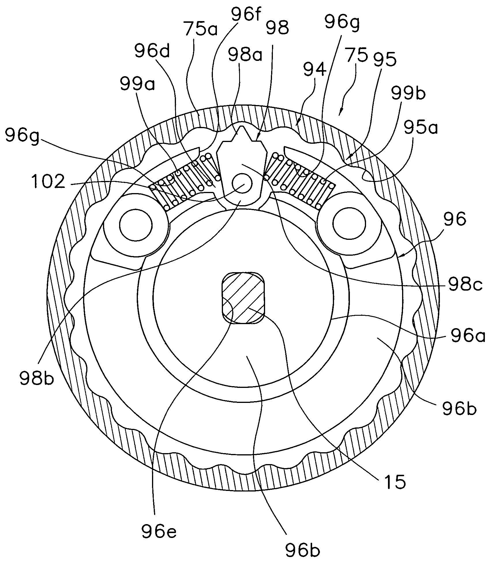
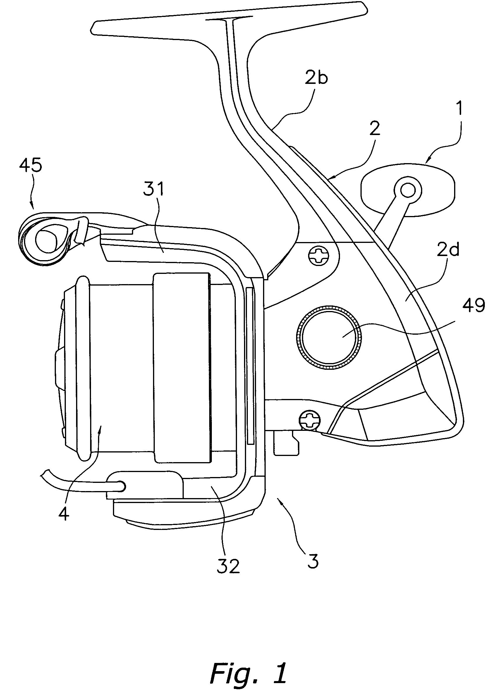
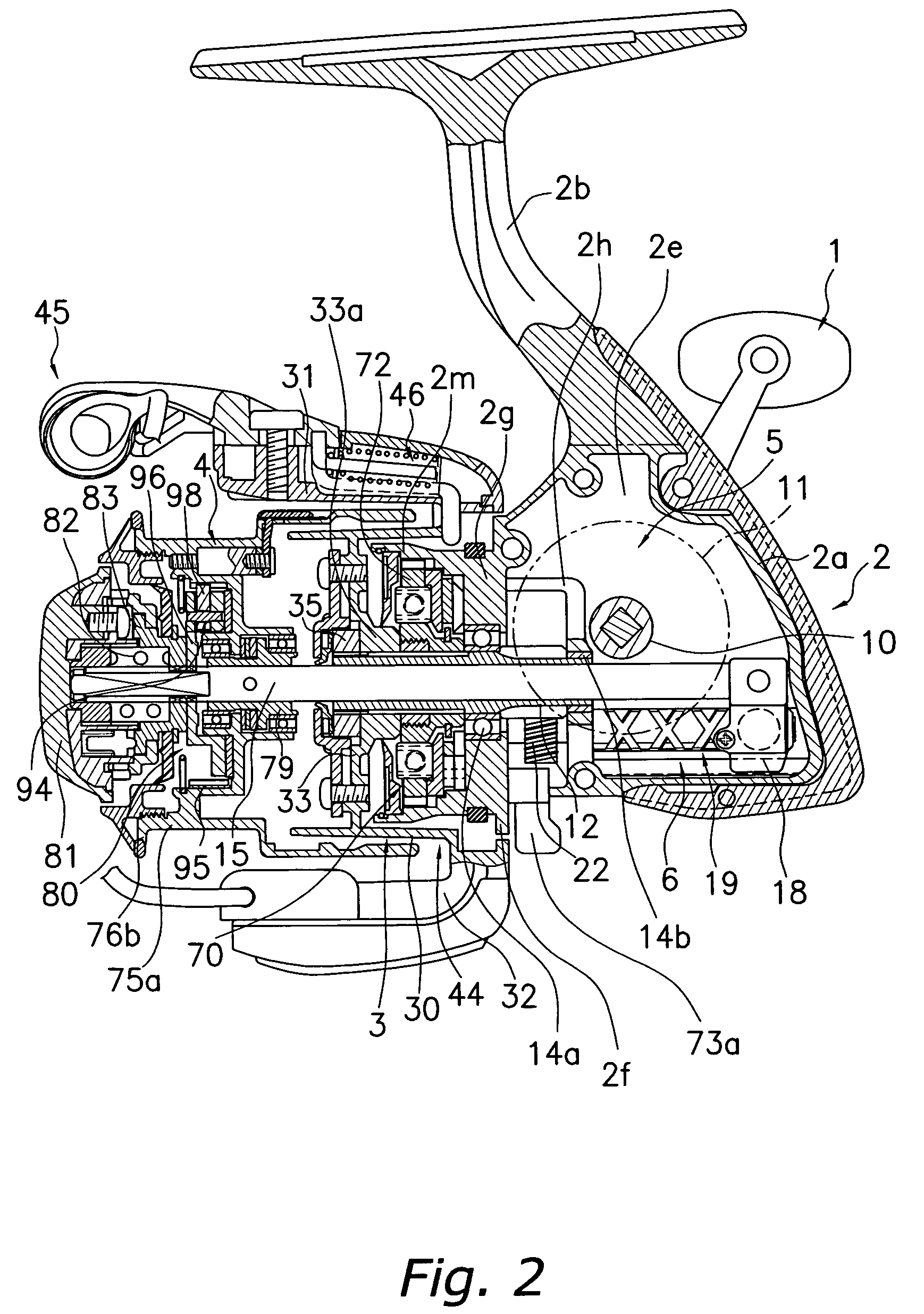
[0051]As shown in FIGS. 1 and 2, a spinning reel in which an embodiment of the present invention is applied includes a handle 1, a reel unit 2 that rotatably supports the handle 1, a rotor 3, and a spool 4. The rotor 3 is rotatably supported on the front of the reel unit 2. The spool 4 has fishing line wound around the outer peripheral surface thereof, and is disposed on the front of the rotor 3 so that the spool 4 can be moved forward and backward. Note that as shown in FIGS. 1 and 2, the handle 1 is mounted on the right side, and the handle cap 49 is mounted on the left side. In FIG. 3, the handl...


PUM


Abstract

A second sounding mechanism includes a first member, a plurality of concave / convex portions that are formed on an inner peripheral surface of the first member to be spaced apart in the circumferential direction, a second member that is non-rotatably mounted on a spool shaft, a pawl member that is arranged on the second member to be pivotable and contactable with the concave / convex portions, and a pair of urging members that are arranged on both sides of the pawl member and urge the pawl member to a central position by pressing on both sides thereof. The tip of the pawl member is arranged to be contactable with the concave / convex portions, and the concave / convex portions repeatedly contact with the pawl member to produce sounds when the spool is rotated. In a sounding mechanism of a spinning reel, the spool can rotate smoothly, while clear, crisp sounds can be obtained.

Description

BACKGROUND OF THE INVENTION[0001]1. Field of the Invention[0002]The present invention relates to a spinning reel sounding mechanism. More specifically, the present invention relates to a spinning reel sounding mechanism that produces sound by relative rotation between a spool that winds up and releases fishing line and a spool shaft.[0003]2. Background Information[0004]A spinning reel generally includes a reel unit that rotatively supports a handle, a rotor, and a spool that is rotatably mounted to a spool shaft. The spool of the spinning reel is movable back and forth with respect to the reel unit, and includes a bobbin portion onto the outer circumference of which fishing line is wound, and a larger diameter skirt portion provided at a rear end of the bobbin portion. A spool mount that restricts rearward movement of the spool is disposed on a rear end portion of the bobbin portion and is non-rotatably mounted to the spool shaft. The interior of the bobbin portion of a front drag t...

Claims


Application Information

Patent Timeline
Patent Type & Authority Patents(United States)
IPC IPC(8): A01K89/02A01K89/01
CPCA01K89/01
Inventor IKUTA, TAKESHI
Owner SHIMANO INC
Learn More