Backlight module
a backlight module and module technology, applied in the field of backlight modules, can solve the problems of affecting the display quality of lcds, bringing roughness and unevenness to the surface of reflectors, and reducing so as to prevent roughness and unevenness of reflectors surface and improve the displaying quality of lcds
- Summary
- Abstract
- Description
- Claims
- Application Information
AI Technical Summary
Benefits of technology
Problems solved by technology
Method used
Image

Examples
first example
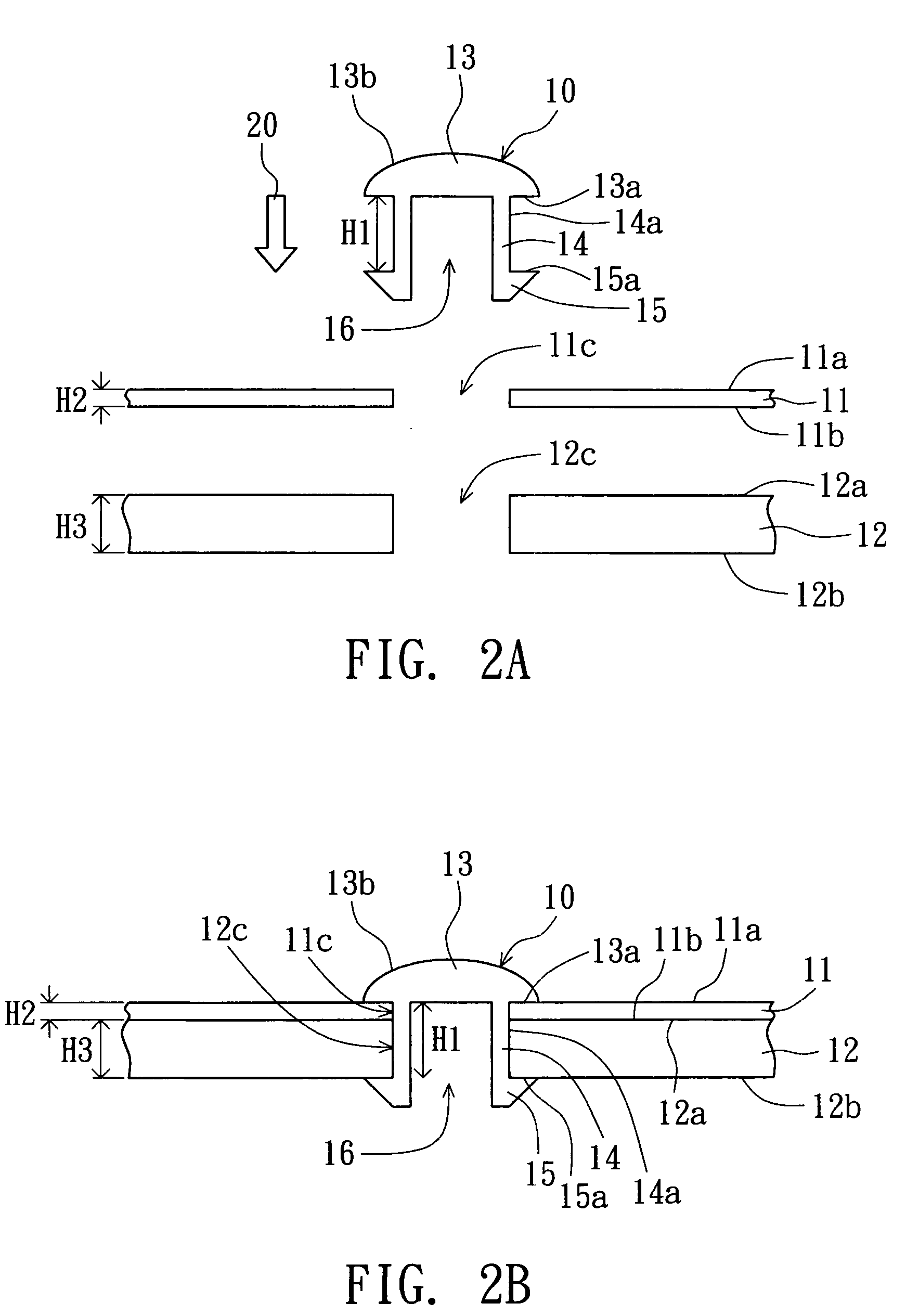
[0026]Referring both to FIG. 2A and FIG. 2B, FIG. 2A is an exploded cross-sectional view showing a backlight module according to the first example of the preferred embodiment of the invention, and FIG. 2B is a combined cross-sectional view showing the backlight module according to the first example of the preferred embodiment of the invention. A backlight module includes a frame 11, a reflector 12 and a holding structure 10 of a backlight module for holding the reflector 11 on the frame 12, instead of using an adhesive attaching the reflector onto the frame conventionally. The reflector 11 has a top surface 11a, an opposite bottom surface 11b, and a through hole 11c which penetrates the top surface 11a and the bottom surface 11b. The frame 12 has a top surface 12a, an opposite bottom surface 12b, and a through hole 12c which penetrates the top surface 12a and the bottom surface 12b. The size of the through hole 11c is corresponding to that of the through hole 12c.
[0027]The holding ...
second example
[0030]Referring to FIG. 3, it is a cross-sectional view showing a holding structure of the backlight module according to the second example of the preferred embodiment of the invention. Most components of the holding structure 30 of the second example are similar to those of the holding structure 30 of the first example except for the second clamp portion 33, so that the symbols used in most components are the same. In FIG. 3, the second clamp portion 33 includes a second surface 13a, a top surface 33b and an external side surface 33c for connecting with the second surface 13a and the top surface 33b. In the second example, the top surface 33b is a flat surface, which means that the second clamp portion 33 can be considered as a cylinder shape structure. Also, the first clamp portion 15, the second portion 33, and the shaft portion 14 can be integrally formed as a bone-shaped or a I-shaped structure, and the material of the holding structure 30 of backlight module includes poly meth...
third example
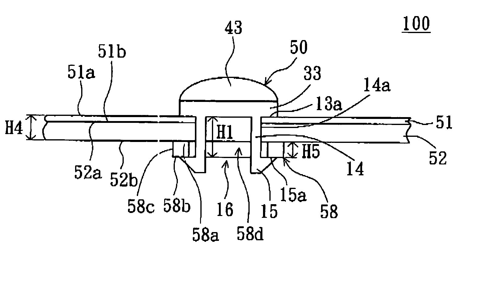
[0031]Referring to FIG. 4, it is a cross-sectional view showing a holding structure of the backlight module according to the third example of the preferred embodiment of the invention. Most components of the holding structure 40 of the third example are similar to those of the holding structure 30 of the second example except for the holding structure 40 further having a cover 43, so that the symbols used in most components are the same. In FIG. 4, the cover 43 has a bottom surface 43a and a top surface 43b, which is connected to the bottom surface 43a. The cover 43 is disposed on the second clamp portion 33 when the bottom surface 43a faces the top surface 43a. The top surface 43b is a bowl-shaped or a hemisphere-shaped structure whose opening faces the bottom surface 43a. That is to say, cover 43 can be considered as an inverted bowl shape or a hemisphere shape structure. Also, the first clamp portion 15, the second portion 33, the cover 43, and the shaft portion 14 can be integra...
PUM
 Abstract
Description
Claims
Application Information
 - R&D
- Intellectual Property
- Life Sciences
- Materials
- Tech Scout
- Unparalleled Data Quality
- Higher Quality Content
- 60% Fewer Hallucinations
Browse by: Latest US Patents, China's latest patents, Technical Efficacy Thesaurus, Application Domain, Technology Topic, Popular Technical Reports.
© 2025 PatSnap. All rights reserved.Legal|Privacy policy|Modern Slavery Act Transparency Statement|Sitemap|About US| Contact US: help@patsnap.com