
Revenue meter with fiber connection

a revenue meter and fiber connection technology, applied in the field of revenue meters, can solve problems such as blackouts, brownouts, or other distribution system problems, and the difficulty of accurately determining and achieve the effect of improving the accuracy of the actual energy delivered to the customer

Inactive Publication Date: 2007-01-02
POWER MEASUREMENT LTD
View PDF75 Cites 54 Cited by
  • Summary
  • Abstract
  • Description
  • Claims
  • Application Information

AI Technical Summary

Benefits of technology

"The present invention is a revenue meter for measuring the delivery of electrical energy from an energy supplier to a consumer through an electric circuit. The revenue meter includes a base and a cover, with at least one sensor operative to sense current in the electric circuit and generate an analog signal indicative thereof. A microprocessor receives the analog signal and computes at least one value therefrom. A fiber optic communications link is coupled to the microprocessor. The technical effect of this invention is to provide a secure and efficient means for measuring electrical energy delivery."

Problems solved by technology

While the fundamental frequency is the frequency that the electrical energy is expected to arrive with, various distribution system and environmental factors can distort the fundamental frequency, i.e., harmonic distortion, can cause spikes, surges, or sags, and can cause blackouts, brownouts, or other distribution system problems.
These problems can greatly affect the quality of power received by the power customer at its facility or residence as well as make accurate determination of the actual energy delivered to the customer very difficult.
To provide user input to the revenue meter, known meters typically utilize cumbersome keys or buttons located within a sealed cover of the revenue meter, or keys which are accessible from the outside but are sealed and cannot be activated without removing the seal.
In addition, a problem exists when keys are added to the meter cover to mechanically actuate the interface of the revenue meter since tolerances in both the manufactured parts and the assembly process can cause an internal structure of the assembled revenue meter to misalign with the cover, for example, lean and twist with relation to the cover, resulting in misalignment of the mechanical actuators with the actual interface of the meter.
Also, with the increasing complexity of revenue meters, usability has often been restricted by the user interface.
Such modifications often cannot be done easily in the field.

Method used


Image

  • Revenue meter with fiber connection
  • Revenue meter with fiber connection
  • Revenue meter with fiber connection

Examples


Embodiment Construction

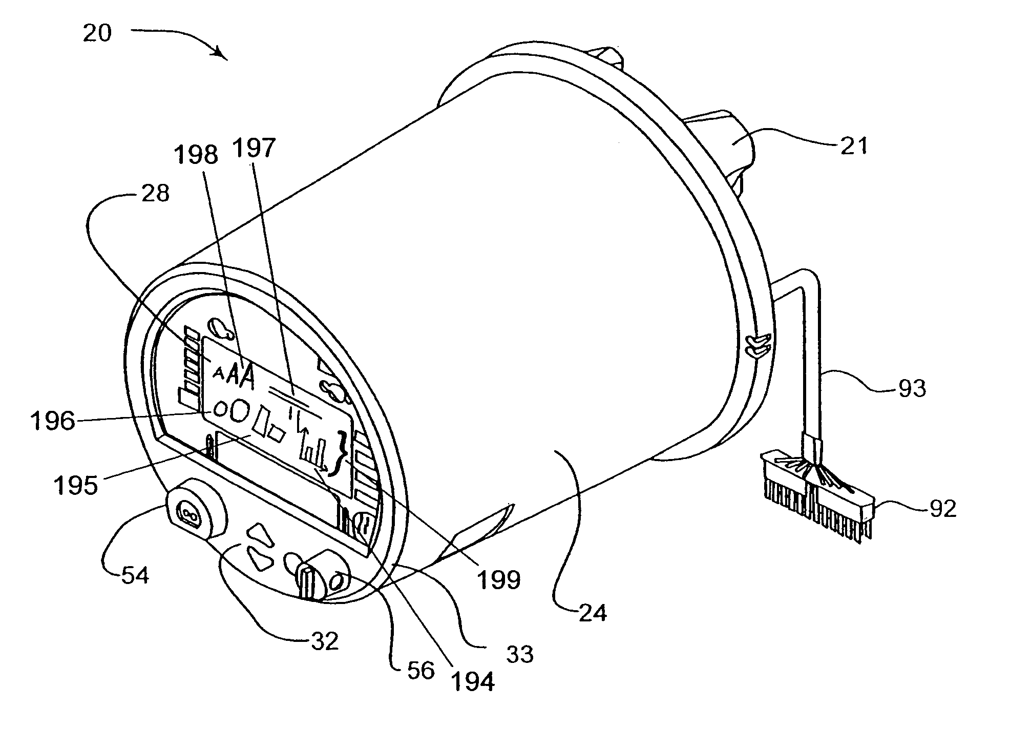
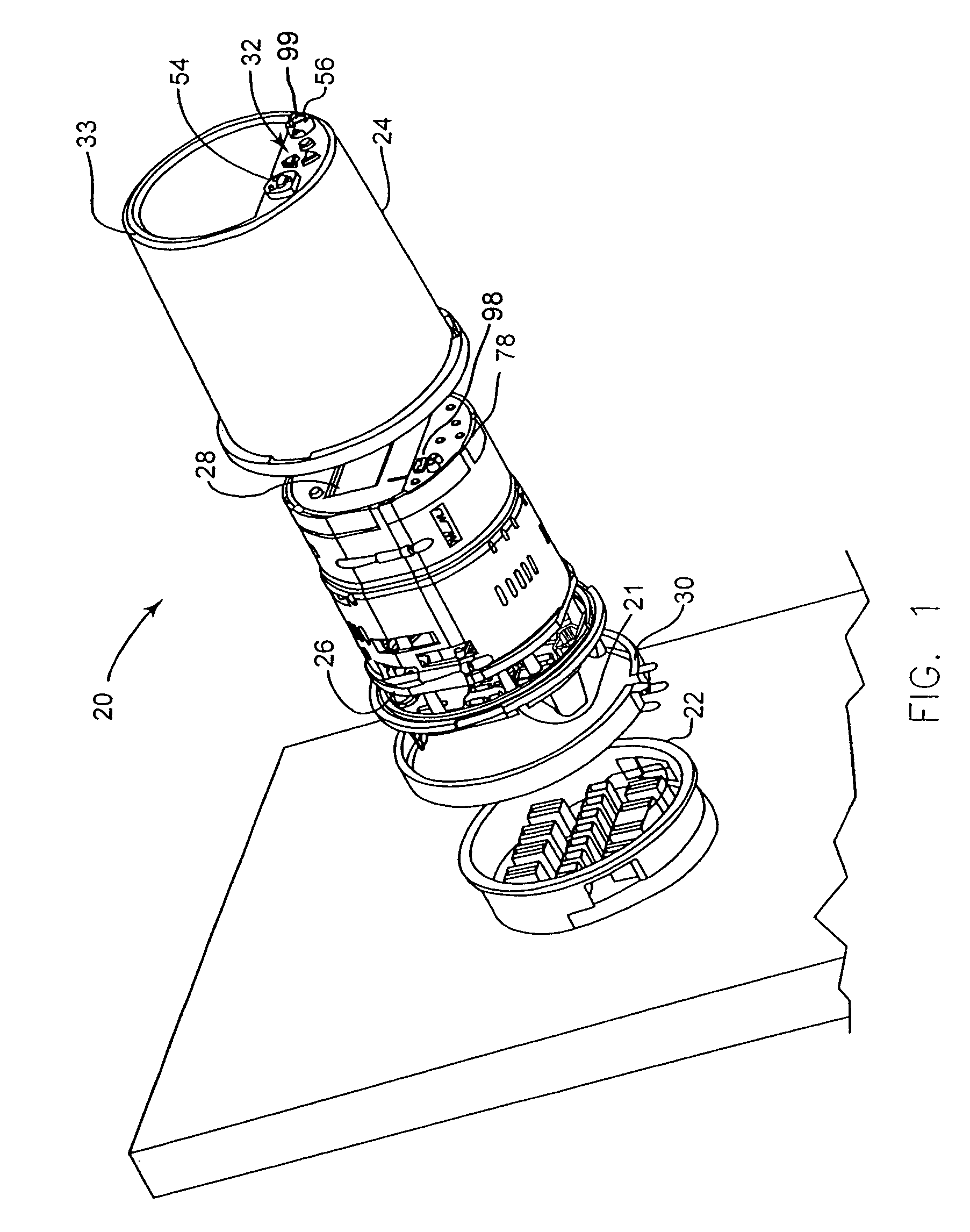
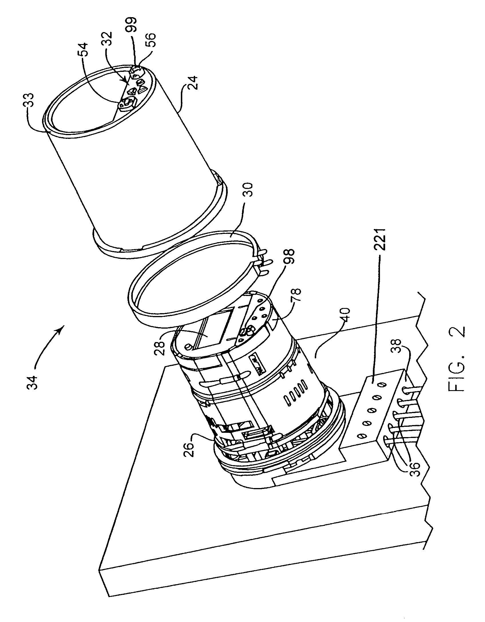
[0064]The disclosed embodiments provide easily accessible and easy to use interfaces that include a front panel keypad, and I / O and communications connections. The keypad allows a user to interact with the meter without requiring a breach to a security seal. For example, the user may need to access a central processing unit (CPU) of the revenue meter to program the meter, to retrieve revenue data, and to retrieve power quality data. In addition, the interface provides an external I / O and communication interface that is expandable and not limited to the number of conductors leaving the revenue meter. Moreover, connection to, and detachment from, the interface is simplified through the use of a single cable protruding from the revenue meter to create the connection.

[0065]The disclosed embodiments relate to revenue accurate electrical meters, including revenue meters with highly accurate and detailed power quality event detection, monitoring and quantification. It will be recognized by...


PUM


Abstract

A revenue meter includes electronics for measuring the delivery of electrical energy from an energy supplier to a consumer through an electric circuit, a display and a cover. The electronics includes at least transducers, an analog to digital converter and logic. A meter cover encloses the revenue meter. Communications of data to and from the revenue meter may be done via a fiber optic communications link.

Description

CROSS REFERENCE TO RELATED APPLICATIONS[0001]This application is a continuation of U.S. patent application Ser. No. 09 / 370,696 filed Aug. 9, 1999, now U.S. Pat. No. 6,825,776 entitled “External I / O and Communications Interface for a Revenue Meter” the entire disclosure of which including the appendices is hereby incorporated by reference. U.S. patent application Ser. No. 09 / 370,696 incorporated by reference the following U.S. patent applications which were filed on same date as that Application, and which are also hereby incorporated by reference:[0002]U.S. patent application Ser. No. 09 / 370,317, “REVENUE METER WITH POWER QUALITY FEATURES”, filed Aug. 9, 1999, now U.S. Pat. No. 6,615,147.[0003]U.S. patent application Ser. No. 09 / 371,883, “A-BASE REVENUE METER WITH POWER QUALITY FEATURES”, filed Aug. 9, 1999, now U.S. Pat. No. 6,493,644.[0004]U.S. patent application Ser. No. 09 / 370,695, “REVENUE METER WITH GRAPHIC USER INTERFACE”, filed Aug. 9, 1999 (abandoned).[0005]U.S. patent appl...

Claims


Application Information

Patent Timeline
Patent Type & Authority Patents(United States)
IPC IPC(8): G08B23/00G01R11/04H04Q9/02
CPCG01R22/065H04Q9/02H04Q2209/826H04Q2209/30H04Q2209/60
Inventor LIGHTBODY, SIMON H.COWAN, PETER C.GILES, DAVID W.JONKER, RENE T.HIRSCHBOLD, MARKUS F.
Owner POWER MEASUREMENT LTD
Learn More