Centrifugal pump with multiple inlets

a centrifugal pump and inlet technology, applied in the field of centrifugal pumps, can solve problems such as clogging of the pump or compromising its operation in other ways

Inactive Publication Date: 2007-01-02
GORMAN RUPP COMPANY THE
View PDF18 Cites 18 Cited by
  • Summary
  • Abstract
  • Description
  • Claims
  • Application Information

AI Technical Summary

Benefits of technology

[0012]According to another feature of the invention, the radial inlet port is arranged such that when it is not being used as an inlet, it can be used to provide access to the impeller chamber in order to remove clogs, debris, etc.

Problems solved by technology

Occasionally, a pump may ingest solid material which can cause clogging of the pump or compromise its operation in other ways.

Method used


Image

  • Centrifugal pump with multiple inlets
  • Centrifugal pump with multiple inlets
  • Centrifugal pump with multiple inlets

Examples


Embodiment Construction

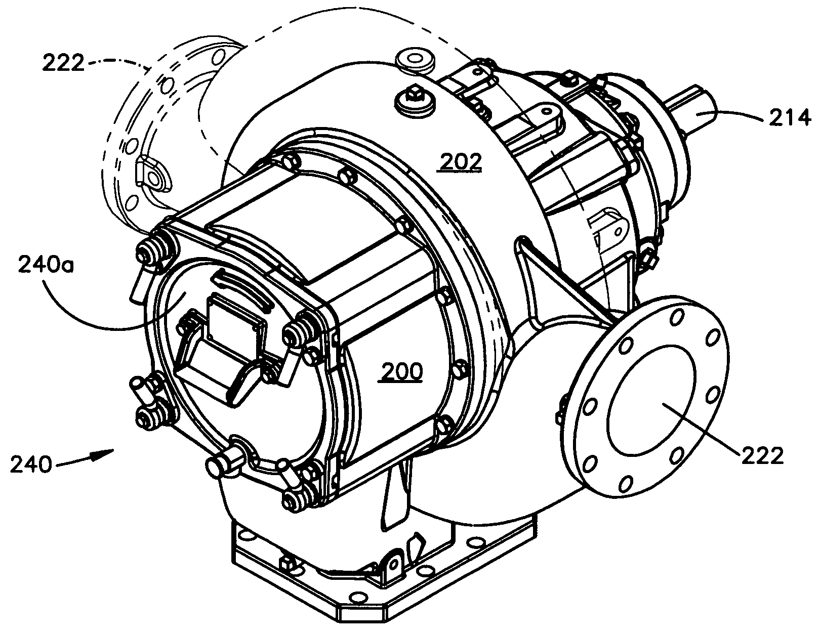
[0030]FIG. 1 illustrates an overall view of a centrifugal pump and drive system constructed in accordance with a preferred embodiment of the invention. As seen in FIG. 1, the system includes a centrifugal pump indicated generally by the reference character 10 which is attached to and driven by a drive unit 12. In the illustrated embodiment, the drive unit includes an internal combustion engine 14 supported by a base 16. Controls indicated generally by the reference character 20 are also attached to the base, as well as other drive components (not shown in detail), which operatively connect the engine 14 to the centrifugal pump 10.

[0031]Referring also to FIG. 2, the centrifugal pump 10 includes a discharge port or outlet 30 (shown best in FIG. 1) and two inlet ports indicated generally by the reference characters 32, 34 (and shown best in FIG. 2). As will be explained, either port 32, 34 can serve as an inlet to the pump.

[0032]As seen in FIG. 2, the unit is shown with a discharge che...


PUM


Abstract

A centrifugal pump assembly that includes an inlet housing that defines a inlet chamber and at least one inlet port in fluid communication with the inlet chamber. A volute forming part of the assembly defines an outlet port. An impeller is mounted for rotation at least partially within the volute and operative upon rotation to convey fluid from the inlet port to the outlet port. The inlet housing defines mounting structure by which the inlet housing can be secured to the volute in any one of a plurality of positions with respect to the volute so that the spatial relationship between the inlet port and the outlet port can be changed by changing the relative position of the inlet housing with respect to the volute. The inlet housing also mounts a pump insert which may be either a dedicated clean-out assembly or structure defining an axial inlet port. The inlet housing defines a mounting flange that includes a plurality of symmetrically spaced apertures and the volute includes structure that is engageable with the flange and includes a plurality of symmetrically spaced bores that are alignable with the apertures formed in the mounting flange in several relative positions. The inlet housing may also be fitted with a aperture in an inlet housing wall for defining a radial inlet port communicating directly with the inlet chamber. Alternately, the inlet housing can include a passage for communicating a spaced inlet port with the inlet chamber. The passage may be jogged. The passage should be such to make the radial inlet and the radial outlet share a common plane, perpendicular to the axis of the impeller shaft. The impeller may form part of a rotating assembly which includes a mounting structure that enables the volute to be secured to the rotating assembly in any one of several positions.

Description

RELATE BACK[0001]This application is a Continuation-in-Part of application Ser. No. 10 / 181,913, filed on Jul. 24, 2002, now U.S. Pat. No. 6,799,943 which is a 371 of PCT / US01 / 02494, filed Jan. 25, 2001, which claims benefit of provisional application Ser. No. 60 / 178,174, filed Jan. 26, 2000. This application also claims priority from Ser. No. 10 / 794,400, filed Mar. 8, 2004, entitled Stacked Self-Priming Pump And Centrifugal Pump.TECHNICAL FIELD[0002]The present invention relates generally to fluid pumps and, in particular, to a centrifugal pump having multiple inlets.BACKGROUND ART[0003]Centrifugal pumps are well known in the art and are used for many fluid pumping applications. For example, centrifugal pumps may be used to pump water from one water station to another. They may also be used in construction applications, i.e., to pump water from an excavation cite.[0004]Occasionally, a pump may ingest solid material which can cause clogging of the pump or compromise its operation in ...

Claims


Application Information

Patent Timeline
Patent Type & Authority Patents(United States)
IPC IPC(8): F04D29/42F04D7/04F04D29/16F04D29/70
CPCF04D7/04F04D29/708F04D29/426F04D29/167F04D29/4293
Inventor RACER, DONALD W.KEITH, MICHAEL L.
Owner GORMAN RUPP COMPANY THE
Why Eureka
Try Eureka