
System for visualizing images to viewers in motion

a visualization system and motion technology, applied in the field of systems for visualizing images to viewers in motion, can solve the problems of affecting the application of prior art, and affecting the effect of visualizing images

Inactive Publication Date: 2007-01-02
MAO XIAOGANG
View PDF10 Cites 7 Cited by
  • Summary
  • Abstract
  • Description
  • Claims
  • Application Information

AI Technical Summary

Benefits of technology

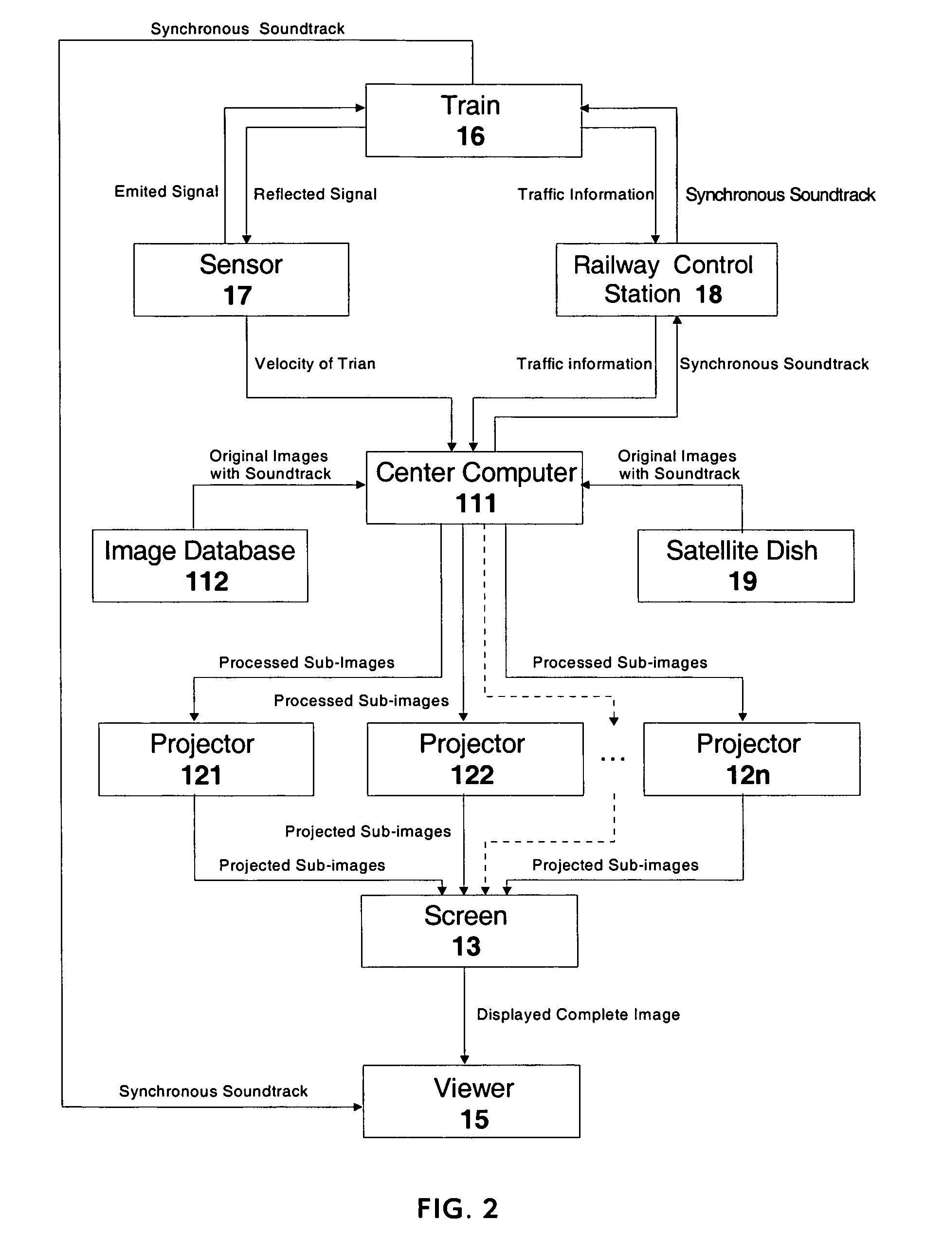
[0019]Besides visualizing an animated image on a screen by a sequence of projectors, the present invention thus also makes it possible to visualize an animated image direct on a sequence of adjacent electronic displaying panels, such as LED or LCD, etc. By means of the present invention it is possible to display up-to-date traffic information by linking the apparatuses to the railway control network, and also possible to receive and display television programs with extra apparatuses such as a satellite dish.
[0022]The generation of an animation effect is independent of the moving speed of the viewer, so it is possible to display an animated image to a viewer moving with an arbitrary velocity.
[0025]It is easy and not costly to renew the display content.

Problems solved by technology

However, the aforementioned prior art has the following limitations in application:
If a vehicle speed is too slow compared to the constant speed, a viewer on the vehicle can only see a series of individual still images without animation effect.
If a vehicle speed is too fast, the images turn into a blur to the viewer.
In practice, when a train is slowing down to stop at or speeding up to leave from a train station, its speed is slow and not constant.
In this situation, the known prior art cannot generate a continuous animation from a sequence of still images to the viewers on a moving train, although the sites in the neighborhood of train stations are crucial for displaying the traffic information and advertisements.
Moreover, for most of the prior art, the still images are fixed on the frames, so it costs a lot of work and money to renew the images.

Method used


Image

  • System for visualizing images to viewers in motion
  • System for visualizing images to viewers in motion
  • System for visualizing images to viewers in motion

Examples


Embodiment Construction

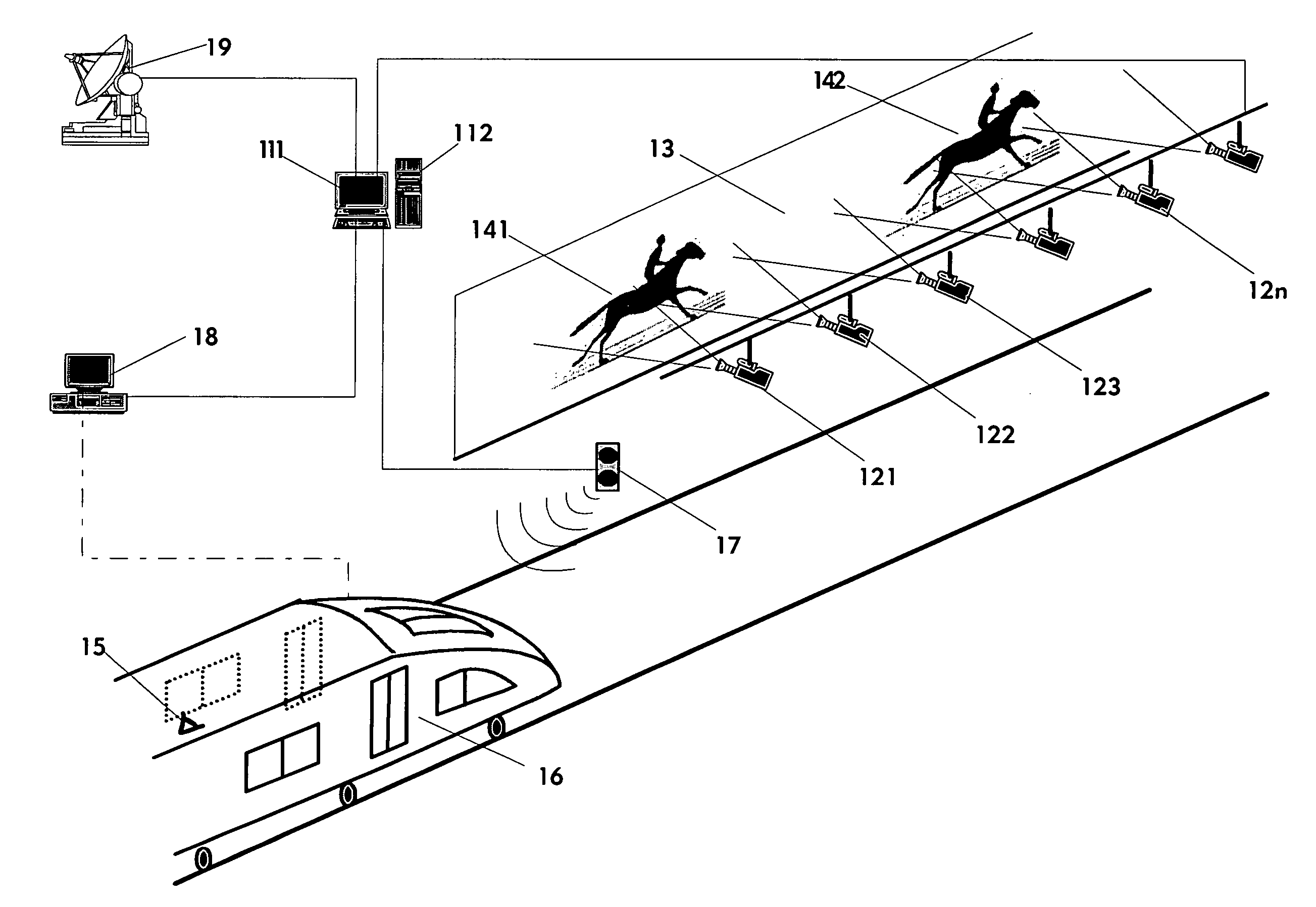
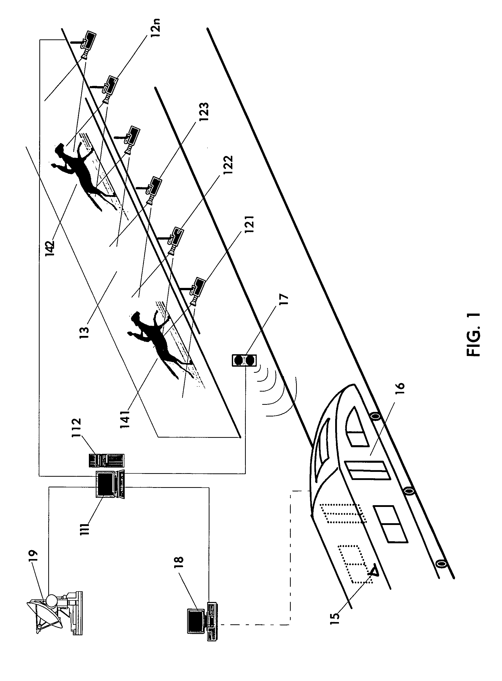
[0032]This invention relates to a new and improved system for visualizing one or more relatively still or animated images to one or more viewers in motion, especially for displaying traffic information or advertisements to the passengers on a train traveling in a tunnel. Instead of using the techniques of the prior art, by which an animation is generated from a sequence of still images as a viewer passes by the images one after another, the present invention uses the principle of conventional movies to generate an animated image and uses a new and improved method to make the display position of the animated image move on an extended span of screen in synchronism with a viewer in motion.

[0033]As an embodiment illustrated in FIG. 1, the apparatuses of the present invention comprise a center computer 111 with an image database 112. An extended span of screen 13 is mounted on a sidewall of a subway tunnel, and another screen could be mounted on another sidewall of the said tunnel if nec...


PUM


Abstract

A system for visualizing one or more images to one or more viewers in motion, comprises:(a) an extended span of screen;(b) a sequence of projectors mounted along the screen;(c) at least one device for receiving a series of images; and(d) a computer for dividing the frame of each image in the series of images into a number of sub-images and shifting the dividing lines on the frame of each image, frame by frame, according to a function of the moving velocity of the viewers, such that the series of images are split into a number of series of shifted sub-images; and(e) projectors for projecting each series of the shifted sub-images on the screen separately by one of the corresponding projectors, such that the images are displayed on the screen, and the display positions move on the screen according to a function of the velocity of the viewers.

Description

BACKGROUND OF THE INVENTION[0001]The invention relates to a new and improved system for visualizing one or more relatively still or animated images to one or more viewers in motion, especially for displaying traffic information or advertisements to the passengers on a train traveling in a subway tunnel.[0002]The conventional principle of generating an animation is known. When a sequence of slightly different images are displayed rapidly one after another, a viewer perceives an animation. In a movie theater, the viewer sits still and the film frames move.[0003]When a viewer is traveling by public transport, such as by train, the near view outside of the windows of the vehicle turns into a blur for the viewer because of the relative movement between the scene and the viewer. In order to display a sharp animated image in synchronism with a viewer in motion, a number of apparatuses and methods have been invented. Prior art includes a sequence of individual image frames mounted beside ra...

Claims


Application Information

Patent Timeline
Patent Type & Authority Patents(United States)
IPC IPC(8): G03B21/00G03B21/26G09F19/22
CPCG09F19/22
Inventor MAO, XIAOGANGHU, LIYA
Owner MAO XIAOGANG
Learn More