
Remote system for monitoring and controlling railroad wayside equipment

a remote system and equipment technology, applied in the direction of railway signalling, point operation from vehicles, transportation and packaging, etc., can solve the problems of not always being able to rely on a train operator to stop a train within the range of the driver's vision, wayside signals subject to normal equipment reliability concerns, and unexpected failures may occur

Active Publication Date: 2006-11-28
GENERAL ELECTRIC CO
View PDF3 Cites 35 Cited by
  • Summary
  • Abstract
  • Description
  • Claims
  • Application Information

AI Technical Summary

Benefits of technology

"The patent describes a system for remotely controlling and monitoring wayside equipment on railways. The system includes a power supply circuit, a central controller, and a transmitter for sending control signals. The system also includes multiple signal devices that communicate with the central controller through a shared media bus. The invention allows for more efficient control and monitoring of wayside equipment, as well as the ability to retrofit existing systems with the new system. The technical effects of the invention include improved efficiency and control of wayside equipment, as well as the ability to retrofit existing systems with the new system."

Problems solved by technology

Such equipment must necessarily be located throughout the railroad system, and is thus geographically dispersed and often located at places that are difficult to access.
Due to the limited field of view from a locomotive and the great inertia of a moving train, it is not always possible to rely on a train operator to stop a train within the range of the driver's vision.
Such wayside signals are subject to normal equipment reliability concerns.
Unexpected failures may occur in spite of such efforts, and such failures may remain undetected for a period of time.
In addition, the maximum distance between a controller and signal equipment is limited to the power carrying capability of the power line.

Method used


Image

  • Remote system for monitoring and controlling railroad wayside equipment
  • Remote system for monitoring and controlling railroad wayside equipment
  • Remote system for monitoring and controlling railroad wayside equipment

Examples


Embodiment Construction

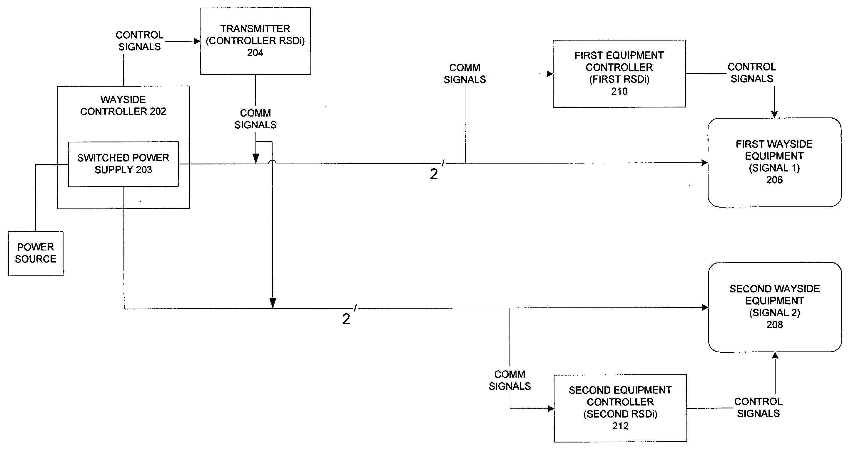
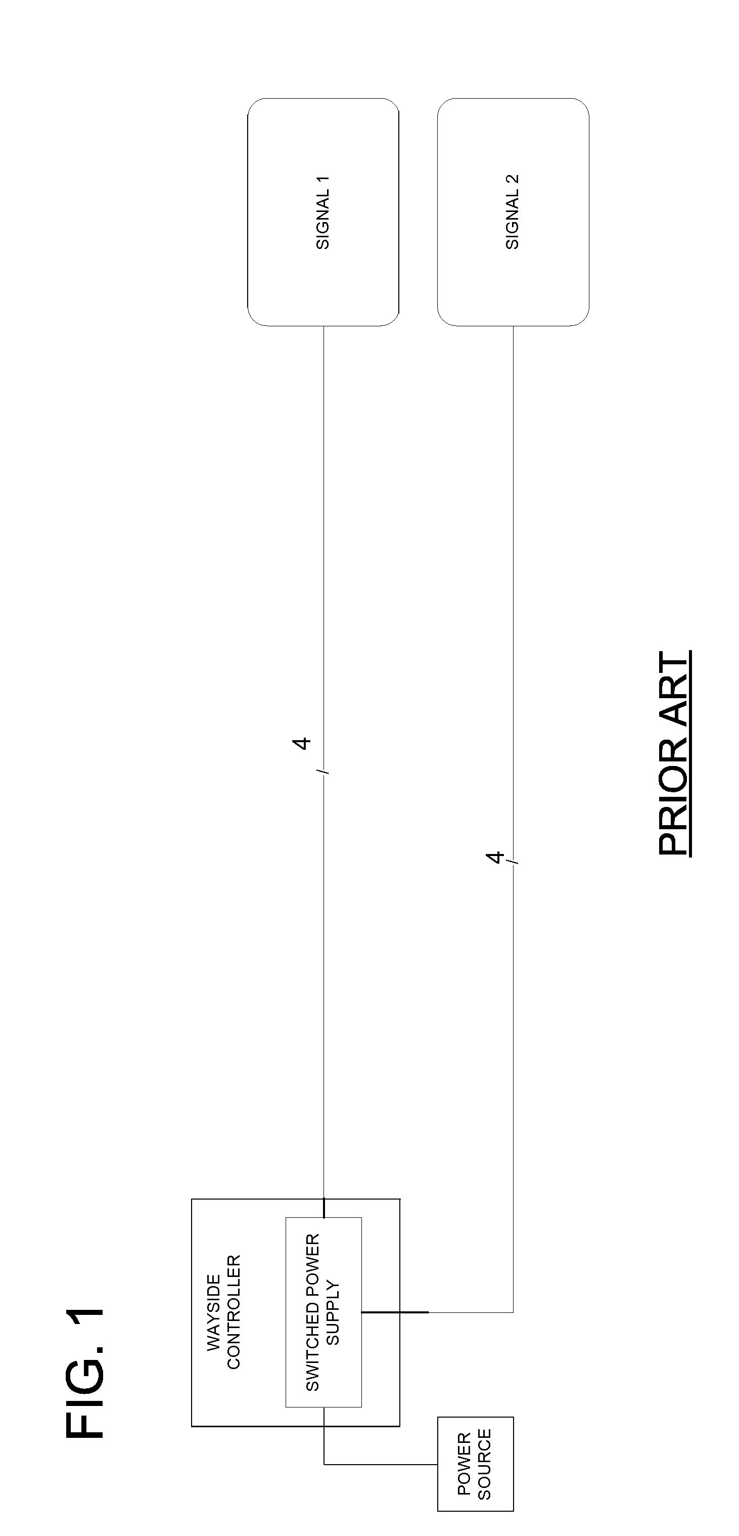
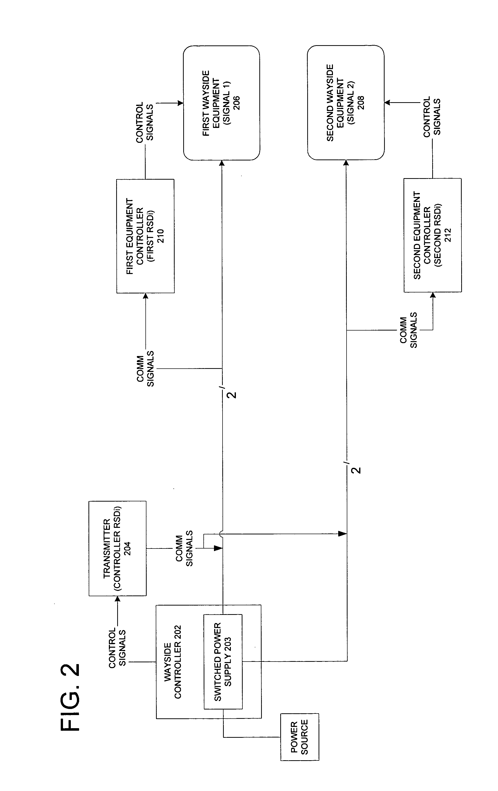
[0029]Referring to FIG. 2, a block diagram of a remote signal driver interface (RSDi) system according to the invention is illustrated. In one embodiment according to the invention, it is contemplate that the system of FIG. 2 would be retrofitted to the existing prior art system of FIG. 1. In the retrofit, only two of the four power lines are employed. In addition, as noted below, the two power lines would carry communication signals between the RSDi and may optionally supply power to each signal when local power is not convenient or available.

[0030]In particular, the control signals from the controller 202 including a switched power supply 203, such as a VHLC, would be provided to a transmitter 204, such as a controller RSDi unit. The transmitter 204 would convert the control signals from the controller 202 into communication signals that would be modulated and transmitted over the two power lines as low power signals to each of a first wayside equipment (e.g., signal 1) 206 and a ...


PUM


Abstract

A system for remote control of an electrically operated railroad wayside equipment having a power supply for powering the wayside equipment. a central controller provides central control signals. A transmitter associated with the controller receives the control signals and transmits communications signals corresponding to the control signals. A remote equipment controller controls operation of the wayside equipment in response thereto.

Description

TECHNICAL FIELD[0001]The invention generally relates to a point to point link between a controller and railroad equipment remote from the controller. In particular, the invention relates to a system for remotely monitoring and controlling a switched electrical power supply which powers electrically operated railroad wayside signaling equipment. Further, the invention relates to a modified power distribution system which powers railroad equipment and a remote control system monitoring and controlling the wayside equipment via the power distribution system.BACKGROUND OF THE INVENTION[0002]Railroad systems include wayside equipment located along the track, such as switches, signals, and vehicle detectors. A wayside equipment may be defined as, for instance, a hot box detector, a hot wheel detector, a dragging equipment detector, a high water detector, a high / wide load detector, an automatic equipment identification system, a highway crossing system, an interlocking controller system, o...

Claims


Application Information

Patent Timeline
Patent Type & Authority Patents(United States)
IPC IPC(8): B61L7/00B61L7/08B61L21/00
CPCB61L7/088B61L27/0005B61L27/70
Inventor MOLLET, SAMUEL R.NOFFSINGER, JOSEPHDAVENPORT, DAVID M.HERSHEY, JOHN E.
Owner GENERAL ELECTRIC CO
Learn More