
In-situ calibration of radar frequency measurement

a radar frequency and in-situ calibration technology, applied in the field of in-situ calibration of radar frequency measurement, can solve the problem that the calibration of the measurement is however difficult to perform

Inactive Publication Date: 2006-11-21
THE UNITED STATES OF AMERICA AS REPRESENTED BY THE SECRETARY OF THE NAVY
View PDF10 Cites 8 Cited by
  • Summary
  • Abstract
  • Description
  • Claims
  • Application Information

AI Technical Summary

Benefits of technology

[0004]Pursuant to the present invention, a radiation reflection blocker is positioned on a targeted surface within the target region before initiating a frequency measurement for a bi-static type of radar system, with forward radiation scattering thereby eliminated. The blocker is then removed during a following measurement test involving vertical adjustment of the receiver of the bi-static radar system in order to determine a diffraction correction factor to be utilized with the previously performed measurement so as to obtain a fully calibrated frequency measurement through a calculator.

Problems solved by technology

Such measurement calibration is however difficult to perform for a bi-static type of radar system, especially when the target surface is close by, because the radar radiation when impinging on the targeted surface it is scattered so as to corrupt the measurement calibration process.

Method used


Image

  • In-situ calibration of radar frequency measurement
  • In-situ calibration of radar frequency measurement
  • In-situ calibration of radar frequency measurement

Examples


Embodiment Construction

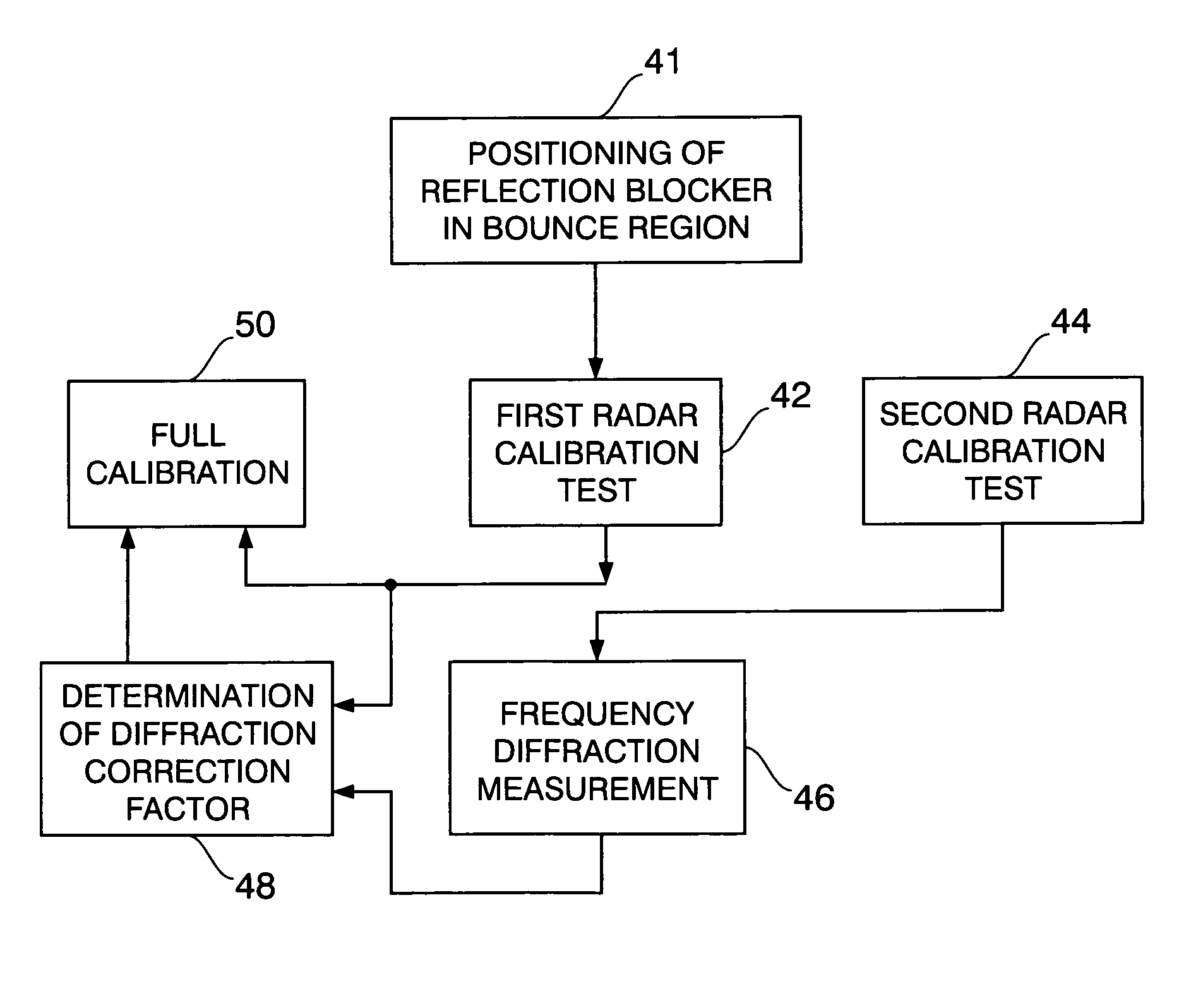
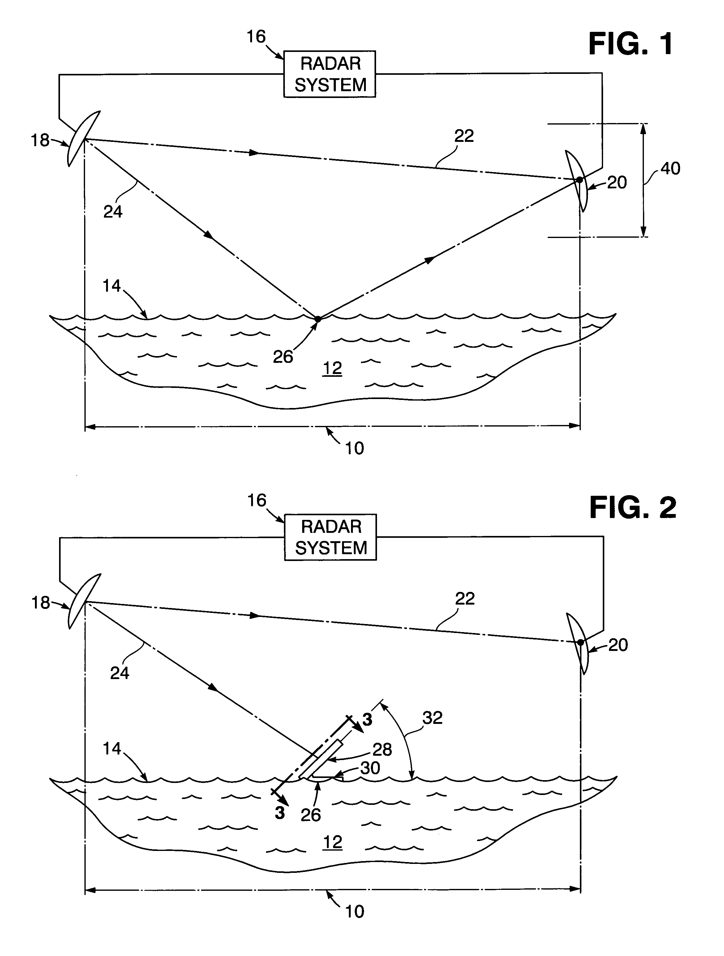
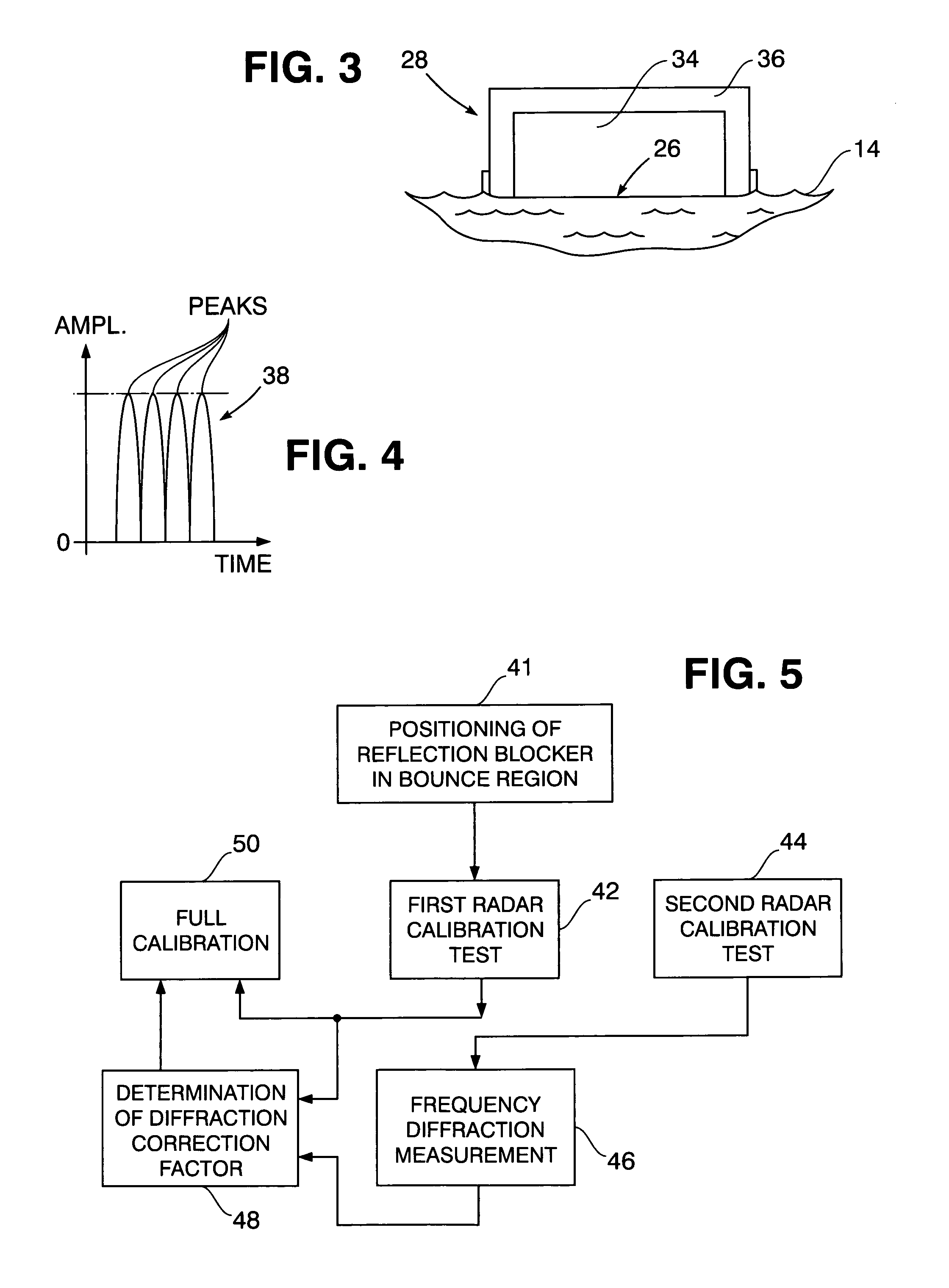
[0011]Referring now to the drawing in detail, FIG. 1 illustrates a target region 10 on top of a body of seawater 12 on which a targeted surface 14 is positioned underlying a bi-static type of radar system 16 located above the targeted surface 14 on some support structure such as a bridge. A radar transmitter 18 and a receiver 20 are associated with the system 16, are located in spaced relation to each other so as to establish the target region 10 therebetween on the seawater surface 14. The transmitter 18 and receiver 20 are furthermore angularly positioned so that during a first initial radiation frequency measurement test, radiation energy is forwardly emitted from the transmitter 18 along a direct path 22 to the receiver 20 and along a radiation scattering path 24 to a radar bounce reflection point 26 on the targeted surface 14 within the region 10.

[0012]Pursuant to the present invention, as shown in FIG. 2 a radar radiation blocker 28 is positioned by a float support 30 on the t...


PUM


Abstract

Frequency calibration of a bi-static type of radar system is performed by positioning radar transmitter and receiver in spaced relation to each other over a targeted seawater surface from which radar radiation along a forward radiation scattering path is reflected toward the receiver while radar energy is also radiated along a direct path to the receiver by-passing the seawater during sequential frequency measurement tests to determine a frequency diffraction factor. A radiation blocking barrier is positioned by a floating support at a reflection location at an angular position on the seawater surface for intersection by the forward scattering path to block reflection of radar energy radiation toward the receiver during one of the measurement tests.

Description

[0001]The present invention relates generally to calibration of frequency measurement of radiation from a bi-static forward radiation scattering type of radar system.STATEMENT OF GOVERNMENT INTEREST[0002]The invention described herein may be manufactured and used by or for the Government of the United States of America for governmental purposes without the payment of any royalties thereon or therefore.BACKGROUND OF THE INVENTION[0003]During operation of a radar system over a targeted radiation reflective surface such as terrain or seawater, the radar energy emitted from the transmitter is reflected from the targeted surface along a forward scattering path toward the receiver. The radar energy is also directly transmitted to the receiver along a line-of-sight path. Typically radar frequency measurement is calibrated for a mono-static type of radar system, wherein the targeted surface is illuminated by the emitted radar energy radiation a known distance from the transmitter and the co...

Claims


Application Information

Patent Timeline
IPC IPC(8): G01S7/40
CPCG01S7/4004G01S13/003
Inventor SMITH, JR., JERRY ROSSON
Owner THE UNITED STATES OF AMERICA AS REPRESENTED BY THE SECRETARY OF THE NAVY
Learn More