
Multiple-use, stimulation-accommodating connector

a multi-use, stimulation-accommodating technology, applied in the direction of coupling contact members, coupling device connections, diagnostic recording/measuring, etc., can solve the problems of noise intruders, impedance mismatches, and conventional connection systems such as those used with apparatus for monitoring brain tissue, to achieve rapid and accurate electrical hookup, easy and fast electrical connection, and simple construction and operation

Inactive Publication Date: 2006-11-14
TECH MEDICAL INSTR
View PDF15 Cites 22 Cited by
  • Summary
  • Abstract
  • Description
  • Claims
  • Application Information

AI Technical Summary

Benefits of technology

The system enables rapid, accurate, and reliable electrical hookup of large numbers of electrodes and lead wires during surgical procedures, reducing noise and error, and allowing simultaneous monitoring and stimulation without disrupting external equipment.

Problems solved by technology

Conventional connection systems such as those used with apparatus for monitoring brain tissue are not adapted for selective direct connection of probes and the like to individual conductors, such as for applying stimulation signals.
Similarly, impedance mismatches can occur when a probe or the like is not properly placed.
In addition, noise may be allowed to intrude as a result of inefficiencies and poor electrical design of such conventional systems, and logistical problems may be created, such as by use of adapters, extra wiring, etc.
Further, conventional systems are not adapted for use with magnetic resonance imaging (MRI) concurrently with epileptogenic monitoring.
Disconnection of a first connector and connection of a second connector takes time, and creates the opportunity for error and equipment breakage.
Additional problems with conventional systems may occur due to extra setup time, extra procedures and their resultant cost, setup complexity and resultant possibility for error such as incorrect hookup, additional problems of open circuits and short circuits, etc.

Method used


Image

  • Multiple-use, stimulation-accommodating connector
  • Multiple-use, stimulation-accommodating connector
  • Multiple-use, stimulation-accommodating connector

Examples


Embodiment Construction

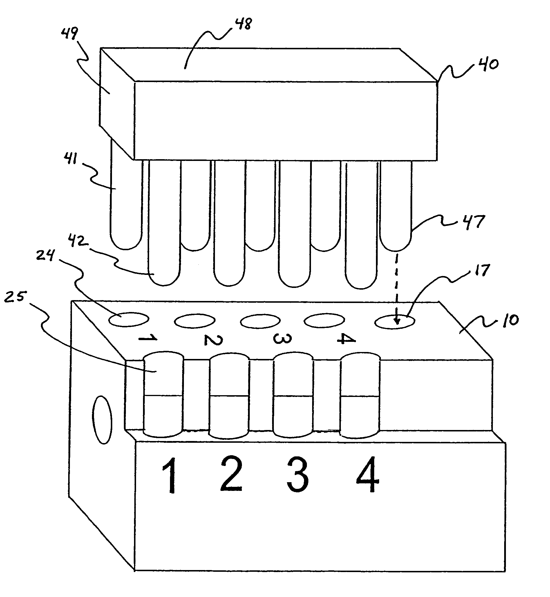
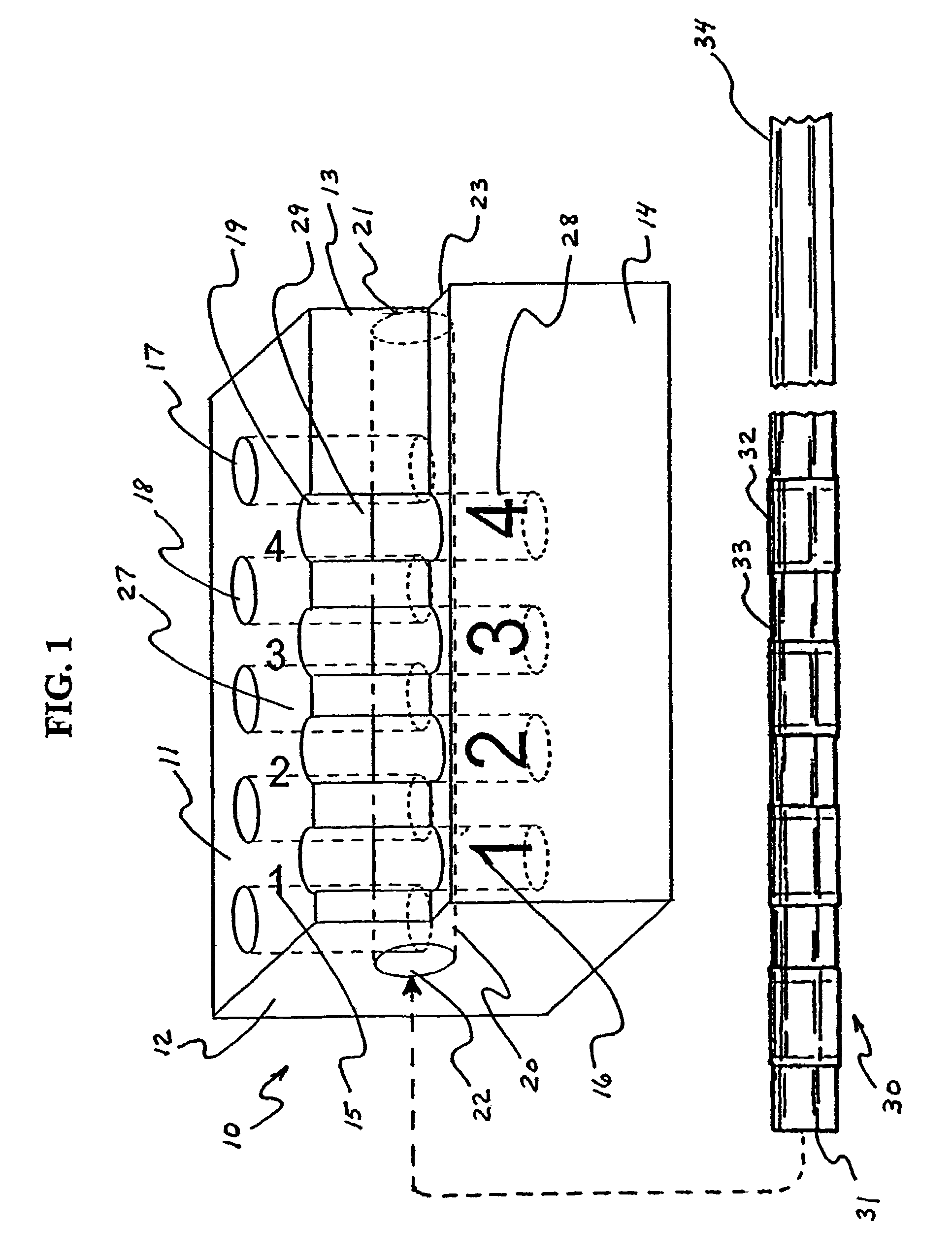
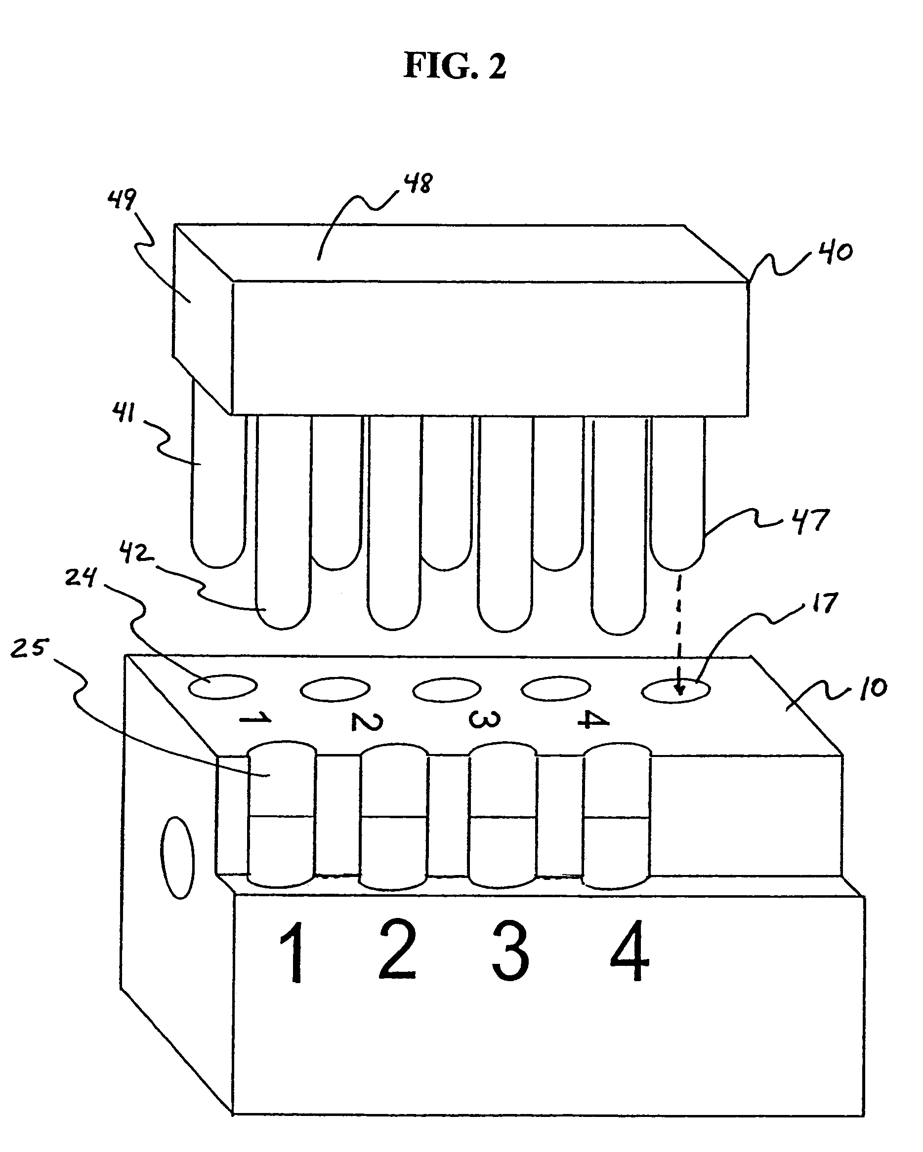
[0039]FIG. 1 shows a connector 10 and a multi-conductor tail 30 for insertion into connector 10, according to an exemplary embodiment of the invention. FIG. 2 shows connector 10 together with a plug 40 adapted for insertion into the connector. FIGS. 3–6 show exemplary embodiments of subdural strip and grid type electrodes used in surgical procedures and having multi-conductor tails with a form similar to that of tail 30. Although not shown, the various embodiments of the invention may also each be used with various other electrodes such as depth electrodes and the like.

[0040]Connector 10 may be formed using a variety of readily available parts and materials, and is preferably formed by a molding or machining process using a polysulfone or polycarbonate resin. A suitable material is the polycarbonate resin known as LEXAN, available from General Electric, Schenectady, N.Y. Preferably, connector 10 is formed with such material being substantially transparent. Use of a substantially tra...


PUM

PropertyMeasurementUnit
diameteraaaaaaaaaa
diameteraaaaaaaaaa
diameteraaaaaaaaaa

Abstract

A multiple-use connection system includes an elongate body having an axial tail-receiving passage and having lengthwise sides, and at least two essentially parallel rows of axially-spaced pin receptacles transverse to the tail-receiving passage, the pin receptacles of one of the parallel rows being exposed along one of the lengthwise sides. A patchbay for selectively connecting pairs of connector pins with ones of a plurality of tail conductors includes an insulating body having an axial passageway adapted for receiving a tail and having pairs of aligned pin receptacles, the pairs of pin receptacles being axially spaced from one another, one pin receptacle of each of the pairs of pin receptacles having an exposed portion adapted for being directly probed, where selective placement of pairs of aligned pins into the insulating body effects electrical connection of a pair of pins to a selected one of the tail conductors.

Description

FIELD OF THE INVENTION[0001]The invention relates generally to devices for providing electrical connection between conductors and, more particularly, to connectors facilitating probing or stimulating chosen conductors being connected.BACKGROUND OF THE INVENTION[0002]Accurate sensing of intracranial electrical activity, such as for determining epileptogenic foci or otherwise, may require use of a plurality of brain contacts. Epileptogenic mapping is one example of the use of electrical devices with tissue-engagement contacts. Examples of two kinds of intracranial electrical contact devices are depth probes and flexible flat surface members.[0003]Depth probes, which may be referred to as “depth electrodes,” penetrate deep into the brain tissue. On the other hand, flexible flat surface members, including what are sometimes referred to as “strip” electrodes and “grid” electrodes, may be placed subdurally in direct contact with brain tissue at the surface of the brain.[0004]Each of these...

Claims


Application Information

Patent Timeline
Patent Type & Authority Patents(United States)
IPC IPC(8): H01R13/10
CPCA61B5/04001A61N1/0529A61N1/0531A61B2562/227Y10T29/49174Y10T29/49176Y10T29/49117Y10T29/49201Y10S439/909A61B5/24A61B5/273
Inventor PUTZ, DAVID A.
Owner TECH MEDICAL INSTR
Learn More