
Joint replacement methods and apparatus

a joint replacement and joint technology, applied in the field of joint replacement methods and apparatuses, can solve the problems of inability to stabilize the block and the inability to achieve stable block stabilization, and achieve the effect of improving the stability of the block

Inactive Publication Date: 2006-10-31
MEDIDEA
View PDF41 Cites 64 Cited by
  • Summary
  • Abstract
  • Description
  • Claims
  • Application Information

AI Technical Summary

Benefits of technology

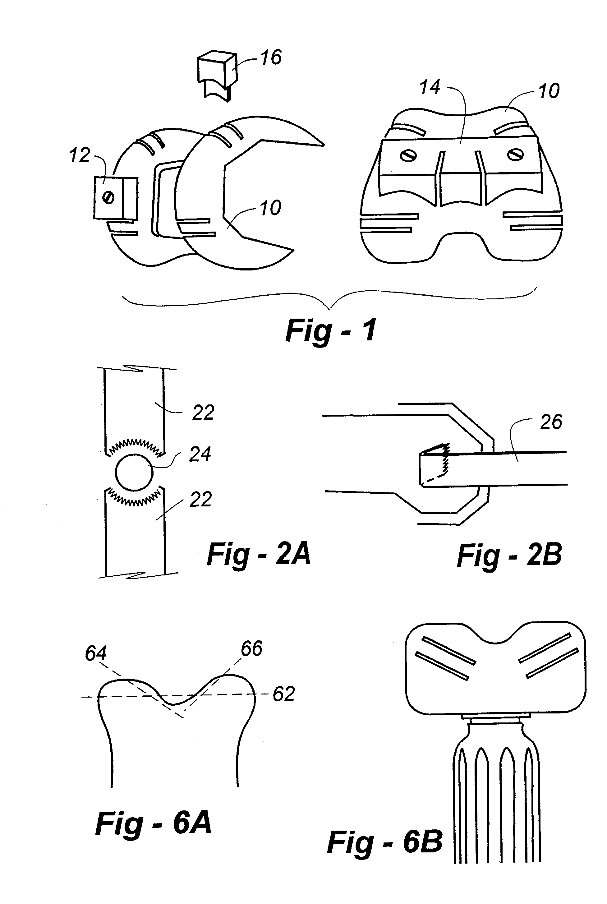
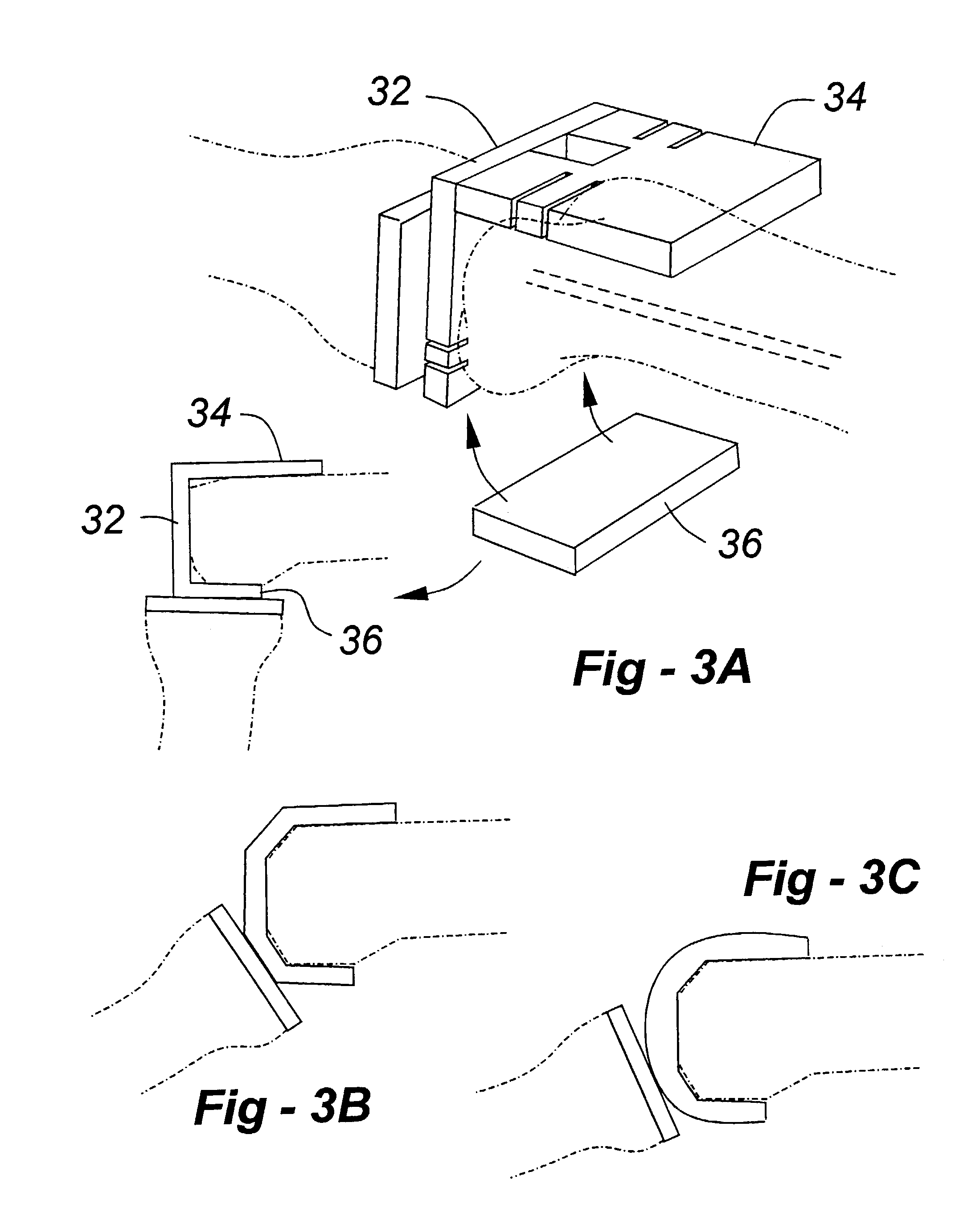
"The present invention is a continuation and improvement of the invention described in U.S. Pat. No. 5,7 16,361, which is about a combination trial / cutting guide for use in orthopedic joint surgeries such as knee, hip, shoulder, and others. The invention provides stabilizers that can be attached to the cutting guide to make it longer and more stable for use with a cutting device. It also provides differently shaped saw blades for making box cuts and other types of cuts. The invention also includes methods for approaching the box cuts and augment cuts from a distal perspective, both laterally and medially. Additionally, the invention provides a trial / cutting guide with flat surfaces for articulation within a joint. The invention also includes a device for determining the joint line relative to a tibia using the fibula as reference."

Problems solved by technology

Cutting blocks are also typically used in revision procedures, though bone deficiency often renders stabilization of the block impossible.
Though such approaches improve bone cutting accuracy, there remains an unacceptable margin of error, the correction of which in some cases requiring a freehand shaping of the bone.

Method used


Image

  • Joint replacement methods and apparatus
  • Joint replacement methods and apparatus
  • Joint replacement methods and apparatus

Examples


Embodiment Construction

[0018]The present invention extends and, in certain instances, improves upon apparatus and methods disclosed and claimed in U.S. Pat. No. 5,716,361, which issued Feb. 10, 1998, entitled BONE CUTTING GUIDES FOR USE IN THE IMPLANTATION OF PROSTHETIC JOINT COMPONENTS. Accordingly, the entire contents of this patent are incorporated herein by reference. Broadly, the '361 patent relates to combination trial / cutting guides, and methods of using the same, in various orthopedic joint situations such as the knee, hip, shoulder, and other areas of the body. The apparatus resides in a shaped body having an inner surface adapted for temporary placement against a bone surface and an outer surface configured to co-act in a joint, for example, as part of a trial reduction. The present invention is directed toward apparatus and surgical techniques which augment or supplant certain teachings of the '361 patent with respect to alternative cutting fixtures and resection accuracy and stability. The var...


PUM


Abstract

Apparatus and surgical techniques provide alternative cutting fixtures and other features to improve bone resection accuracy and joint stability. According to one embodiment, stabilizers are removably attached to a cutting guide to temporarily lengthen the surface against which a saw or other cutting device rests. Another embodiment provides differently shaped saw blades, having curved distal ends and right-angle bends applicable to box cuts of the type associated with cruciate sacrifice knee-replacement surgery. Methods are also disclosed whereby the box cuts, distal and posterior augment cuts may be approached from a distal perspective, both laterally and medially. A different embodiment provides a trial / cutting guide having flat surfaces as opposed to curved surfaces adapted for articulation within a joint. Yet a further alternative embodiment teaches a device for determining the joint line relative to a tibia using the fibula as reference.

Description

REFERENCE TO RELATED APPLICATION[0001]This application is a divisional of U.S. Pat. application Ser. No. 09 / 159,168, filed Sep. 23 1998, now U.S. Pat. No. 6,488,687 which claims benefit of U.S. provisional application No. 60 / 059,804, filed Sep. 23, 1997; and the current application is a continuation-in-part of U.S. Pat. application Ser. No. 09 / 300,665, filed Apr. 27, 1999 now U.S. Pat. No. 6,602,259 which is a continuation of U.S. Pat. application Ser. No. 08 / 937,216, filed Sep. 18, 1997, now U.S. Pat. No. 5,897,559.FIELD OF THE INVENTION[0002]This invention concerns arthroplasty, and, more particularly, resides in improved cutting guides and techniques to better assist a surgeon in preparing a bone, for example, to receive an implant.BACKGROUND OF THE INVENTION[0003]Whether for primary or revision arthroplasty, cutting guides are typically employed to ensure that the bone saw performs resections corresponding to mating surfaces of the prosthetic component. For example, in a femoral...

Claims


Application Information

Patent Timeline
Patent Type & Authority Patents(United States)
IPC IPC(8): A61B17/56A61F2/38A61B17/15
CPCA61B17/154A61B17/155A61B17/157
Inventor MASINI, MICHAEL A.
Owner MEDIDEA
Learn More